3
Aufbaubeschreibung
Assembly Instructions
Please use protective gloves - Sharp edges and corners can cause injury. Broken glass is a safety hazard - always dispose of with care.
Important! When assembling polycarbonate glazing the UV-resistant side is indicated by a plastic folio and printing at the edge. This side must face
outside. Remove the folio before positioning in the profi les. If there are no markings on the glazing then the direction of assembly is not important.
Note! If desired, it is possible to seal the greenhouse at the edges using silicone. Silicone is not in cluded.
Diagrams in a single frame show the view from inside the greenhouse. Those enclosed in a double frame show the view from outside the greenhouse.
Please check that all listed parts are included!
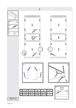
1. Remove existing door and lay to the side. Remove pane 1a and bars (1047), (3096), (3097), (3101) taking care not to damage bars, bolts or the polycar-
bonate pane. In the event that a bolt is damaged, it can be replaced by inserting an included cropped head bolt (2001) into the bolt channel in the bar.
Assemble bars (2096) and (2097) (1.1) (1.2).
Assemble both existing and provided bar (1047) from outside as shown.
Attach bars (2043) between the eaves and bar (1047) using bolt (1001) and nut (1002) at bar (1047) end (1.3), and nut (1002), bolt (1005) and spacer
(1010) at the eave end (1.4) (1.5).
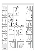
2. Attention: Do not stand the assembled doors on the door gliders (1014) to avoid damaging them.
Unscrew bar (3058) from one side of the existing door.
Push the door gliders (1014) onto both ends of door bars (1060) (2.1).
Assemble the doors as shown taking note of the correct placement of side bars (3098) and (3099) (2.1) - (2.3).
Connect door rollers (1015) to the door bar (1062) using bolt (1004), washer (1009) and nut (1007) (2.4). Bolt door bar (1062) to upper bar (1059) (2.3).
Connect the door fi xer (1111) as shown.
The door rollers can now slide into door runner bars (1047) (2.6) (2.7). Please ensure that the door gliders are also running on the bottom track (2.5). Once
the doors are correctly in place, connect a nut and bolt into the end of door runner bars (1047) as door stoppers.
Adjust the doors so that they move freely.
3. Please note the already mentioned safety precautions.
Press the glazing seals (1020) onto the aluminium profi les (3.1) (3.2) and cut to length.
Cut the removed polycarbonate pane (3.3) and position panes as shown, fi xing in place using glazing spring clips (1011) (3.2).
* (For Merkur/Neptune models with glass panes: glass panes must be ordered separately)
To give polycarbonate panes extra stability it is recommended to connect them to the bottom of the aluminium profi le, in the middle of each pane, with a
screw (6084) and washer (6083) (3.4). To achieve this it is necessary to drill a 2mm hole through pane and aluminium profi le. The drill is not included.
Bei der Montage sollten Sie immer Handschuhe tragen. Gesplittertes Glas kann zu Verletzungen führen – bitte vorsichtig damit hantieren.
Wichtig! Bei der Polycarbonat Verglasung muss die mit Folie versehene UV- beständige Seite nach außen zeigen. Entfernen Sie die Folie, bevor Sie die
Profi le montieren. Wenn keine Kennzeichnung auf der Verglasung ist, ist es egal, welche Seite nach außen zeigt.
Wenn Sie es wünschen, können Sie das Ge wächshaus an den vorhandenen Fugen mit Silikon abdichten. Das Silikon gehört nicht zum Lieferumfang.
Alle Zeichnungen sind von der Innenseite des Hauses gesehen abgebildet, mit Ausnahme der Abbildungen, die in einem Doppelrahmen darge-
stellt sind. Diese beschreiben die Außenansicht.
Bitte anhand der Teileliste kontrollieren, ob alle Teile beiliegen!
1. Die bereits eingebaute Tür und die Hohlkammerplatte 1a herausnehmen und an die Seite legen. Die Profi le (1047), (3096), (3097) und (3101) demon-
tieren und darauf achten, dass weder die Profi le noch die Schrauben beschädigt werden. Falls eine Schraube beschädigt werden sollte, kann sie ersetzt
werden durch Einschieben einer abgeschnittenen Schraube (2001) in den Schraubenkanal.
Die Profi le (2096) und (2097) (1.1.) (1.2.) befestigen.
Von außen beide Profi le, das bereits vorhandene und das beiliegende Profi l (1047), wie in der Abbildung gezeigt, montieren.
Die Türspurstützen (2043) zwischen Traufe und Profi l (1047) mittels Schrauben (1001) und Muttern (1002) am Profi lende (1047)(1.3) befestigen und
Schraube (1002), Mutter(1005) und Abstandshalter (1010) am Traufenende befestigen (1.4) (1.5).
2. Achtung: Um Beschädigungen zu vermeiden, die zusammengebauten Türen nicht auf die Türgleiter (1014) stellen.
Das Profi l (3058) von einer Seite der bereits vorhandenen Tür losschrauben.
Die Türgleiter (1014) auf beide Endstücke der Türprofi le (1060)(2.1) schieben.
Die Türen wie abgebildet montieren und dabei auf die korrekte Positionierung der Seitenprofi le (3098) und (3099) (2.1)-(2.3) achten.
Die Türrollen (1015) mit dem Türprofi l (1062) verbinden mittels Schrauben (1004), Unterlegscheiben (1009) und Muttern (1007) (2.4). Türprofi l (1062) an
dem oberen Profi l (1059)(2.3) anschrauben. Den Türfeststeller (1111) wie abgebildet montieren.
Die Türrollen können jetzt in die Türlaufschienen (1047)(2.6) geschoben werden. Bitte darauf achten, dass die Türgleiter auch das Bodenprofi l umschließen
(2.5). Türgleiter nicht hineinlegen. Sobald die Türen richtig positioniert sind, eine Schraube und Mutter am Ende der Türlaufschiene (1047) als Türstopper
anbringen. Die Türen justieren bis sie frei laufen.
3. Drücken Sie den Verglasungsstreifen (1020) auf die Stege der senkrechten Aluminiumprofi le (3.1). Schneiden Sie die zur Seite gelegte Hohlkammer-
platte 1a nach den Angaben der Tab. 3.3. Bei Modellen mit Echtverglasung muss das Glas gesondert bestellt werden. Die Verglasung wie in der Abbildung
gezeigt einsetzen und mit Hilfe der Glasfeder-klammern (1011) (3.2) befestigen.
Um den Hohlkammerplatten zusätzliche Stabilität zu geben, wird empfohlen, sie mit dem unteren Aluminiumprofi l zu verbinden, und zwar jeweils in der Mitte
jeder Hohlkammerplatte mittels Schraube (6084) und Unterlegscheibe (6083) (3.4). Um dieses zu erreichen, ist es notwendig, durch Hohlkammerplatte und
Aluminiumprofi l ein Loch von 2 mm zu bohren. Der Bohrer gehört nicht zum Lieferumfang.
015.01.1003


