background image

D-303166 AmberLink™ User Guide 

5


CANCEL

BUTTON

HELP

BUTTON

MICROPHONE

TROUBLE

LED

(Yellow)

STATUS

LED

(Red)

POWER

LED

(Green)

SPEAKER

COMMUNICATION

LED

(Green)

Cancel

Mode


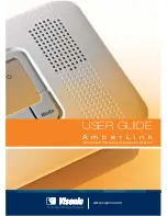
Figure 1 

– Front View 


Figure 2 

– System Configuration 

Содержание AmberLink

Страница 1: ...Wireless Emergency Response System USER GUIDE A m b e r L i n k www visonic com ...

Страница 2: ...D 303166 AmberLink User Guide 1 AmberLink Wireless Emergency Response System User s Guide Cancel Mode ...

Страница 3: ... TO FUNCTION However if the Manufacturer is held liable whether directly or indirectly for any loss or damage arising under this limited warranty THE MANUFACTURER S MAXIMUM LIABILITY IF ANY SHALL NOT IN ANY CASE EXCEED THE PURCHASE PRICE OF THE PRODUCT which shall be fixed as liquidated damages and not as a penalty and shall be the complete and exclusive remedy against the Manufacturer When accept...

Страница 4: ... Reset to Factory Default 14 MOUNTING THE UNIT 15 Mounting the Unit on a Table Fig 4 15 Mounting the Unit on the Wall 15 Using your AmberLink 16 Using your Pendant Transmitter 16 Calling for Emergency Assistance 16 Trouble 17 Remote control by telephone 17 MAINTAINING YOUR SYSTEM 18 Pendant transmitter Test 18 When a Pendant s Battery is Low 18 When a Smoke Detector s Battery is Low 18 Unit Batter...

Страница 5: ...have all the necessary components AmberLink Unit Transformer Input 120VAC 60 Hz Output 9VAC 0 1A Pendant transmitters supplied with necklace Additional Accessories Optional USB Programming Cable or RS 232 Dual Programming Cable and Adaptor Supervised wireless smoke detector MCT 426 Waterproof arm disarm security activation pendant transmitter MCT 201 WP Fully supervised indoor PowerCode flood dete...

Страница 6: ...166 AmberLink User Guide 5 CANCEL BUTTON HELP BUTTON MICROPHONE TROUBLE LED Yellow STATUS LED Red POWER LED Green SPEAKER COMMUNICATION LED Green Cancel Mode Figure 1 Front View Figure 2 System Configuration ...

Страница 7: ...for 3 sec Received RF signal with strong or good RSSI from any enrolled transmitter Blinks Received RF signal with poor RSSI from any enrolled transmitter No light No RF signal received 2 Trouble LED Lights steadily Indicates system trouble Blinks When GSM RSSI is poor No light No trouble 3 Communication LED Light steadily Communication via PSTN GSM is online Blinks Phone line failure or is discon...

Страница 8: ... in the area where you spend most of your time The location should also enable an optimal signal reception for pendants and smoke detectors The Unit can be placed on a table desk or counter It also can be mounted on a wall Make sure that the location you have selected is near an electrical outlet and a phone jack Connect the Unit to your Telephone Line The AmberLink communicates with your Monitori...

Страница 9: ...gure 3a 12 VAC 1 A 120 VAC 120 mA AC Battery Pack Lift plastic cover and insert computer cable Figure 3b Installation Power Telephone and Tel line battery Connection Note It is recommended that the AC power input the Remote Programmer computer connection and the telephone be interconnected within the same room ...

Страница 10: ...tic enrollment of the GSM modem into the AmberLink panel memory GSM modem auto detection is activated after reset device power up CAUTION Make sure that the AmberLink panel is powered OFF and disconnected from the mains power before opening the panel Inserting the GSM Module into the AmberLink Panel 1 Open the battery enclosure on the back cover disconnect the battery and remove it 1 Figure 4a Rem...

Страница 11: ...to the battery enclosure and close the enclosure s cover 4 5 6 Figure 4c Inserting the GSM module Inserting the GSM Module s SIM Card To enable GSM communication with the CMS a standard universal SIM card with Voice and Text in Activated state is required Make sure the SIM card has sufficient voice minutes and SMS allowance before installation Insert the SIM card into the GSM module as described b...

Страница 12: ...g from your authorized Visonic dealer FTP Server location and temporary login details Operator code and password required to install the AmberLink program 1 Log in to the FTP site and enter the AmberLink Software folder 2 Download the contents of this folder to your PC 3 To run the downloaded installation file and continue AmberLink installation enter the AmberLink operator code and password when ...

Страница 13: ...e Power On notification to the Central Station and a Happy Tune plays when you turn the switch off the unit sends a Power Off notification and you hear a Sad Tune Caution When the plug is removed the unit is disconnected from the mains supply and will run on the battery pack When electrical power is supplied the green light on the front panel illuminates Connecting the AmberLink to the Monitoring ...

Страница 14: ...own in Table 1 Flashing light Free location into which a transmitter can be enrolled Steady light Occupied location with an enrolled transmitter Table 1 Zone Number Indication ZONE No LED 1 ON 2 ON 3 ON ON 4 ON 5 ON ON 6 ON ON 7 ON ON ON 8 ON 9 ON ON 10 ON ON 11 ON ON ON 12 ON ON 13 ON ON ON 14 ON ON ON 15 ON ON ON ON 16 Global Zones clear 3 When the LEDs of the desired location flash activate the...

Страница 15: ...system is ready for enrolling Wireless Devices Test 1 Press and hold both the CANCEL button and the right MODE button for 6 seconds All 4 LEDs should flash to indicate that the system is in programming mode Test mode 2 Activate the transmitter you wish to test and listen to the system response If the signal level received by the system is Strong or Good the system will respond with a success beep ...

Страница 16: ...n a table Figure 8 Table Stand Mounting Note The table stand can be easily disassembled by inserting a screwdriver into the rib space of the stand and with the screwdriver pulling the stand away from the unit Mounting the Unit on the Wall 1 Drill 2 holes in the mounting wall and insert wall anchors 2 Insert 2 screws in the wall leave a 5 mm or 0 2 inch gap between the screw heads and the wall 3 Mo...

Страница 17: ...s beep is heard The AmberLink then calls the Monitoring Center or a private phone If your phone is ringing pressing the pendant s red button once will answer the incoming call You can then talk over the unit s speakerphone To end the speakerphone call and hang up simply press the pendant button again Neckband You can wear the pendant transmitter using the neckband Slip the tab on the neckband into...

Страница 18: ...M trouble network failure SIM card problem Remote control by telephone Both the central station and any person to whom the AmberLink unit is dialing can perform a number of actions using the AmberLink unit as follows Pressed button Performs 1 Half duplex speaker ON microphone OFF 3 Half duplex microphone ON speaker OFF 4 Increase speaker volume up to 4 levels 7 Decrease speaker volume up to 4 leve...

Страница 19: ...nable this feature during configuration At the scheduled time the pendant s LED blinks to instruct the user to press the Transmit button to confirm the test LED indicator Velcro strap Transmit Button Loop Figure 10 MCT 212 Pendant When a Pendant s Battery is Low When the MCT 212 pendant transmitter s battery is low its LED flashes rapidly several times per second during transmission When a Smoke D...

Страница 20: ...Battery Replacement Open battery compartment cover see Figure 11 Insert one 8 battery pack and connect its connector to the AmberLink receptacle Route the wire as shown in Figure 11 Battery Compartment Cover Figure 11 Replacing the Battery ...

Страница 21: ... escape planning procedure before holding a fire drill at night while they are asleep The objective here is to perform a fire drill and not to frighten the children so informing the children of the fire drill before they go to bed can be as effective as a surprise drill If children or others do not awaken promptly to the sound of the smoke alarm or if there are infants or family members with mobil...

Страница 22: ...EMPERATURE 301 RESTORE AC POWER 302 LOW BATTERY CONTROL PANEL 308 SYSTEM SHUTDOWN 311 BATTERY DISCONNECTED 344 RF RECEIVER JAMMING 350 COMMUNICATION RESTORE 351 TELEPHONE LINE TROUBLE 373 FIRE DETECTOR TROUBLE 380 GAS TROUBLE 380 PROBE TROUBLE 381 LOSS OF SUPERVISION 383 TAMPER SENSOR 384 LOW BATTERY TRANSMITTER 393 FIRE DETECTOR NEEDS CLEANING 401 SYSTEM ARMED AWAY 441 SYSTEM ARMED HOME 459 RECEN...

Страница 23: ...MITTER XS TRANSMITTER LOST SUPERVISION XJ RESTORAL TO TRANSMITTER LOST SUPERVISION TA TAMPER ALARM TR TAMPER RESTORE MA MEDICAL ALARM NECK PENDANT AND WATCH MT MEDICAL TRANSMITTER LOW BATTERY MR RESTORAL TO MEDICAL TRANSMITTER LOW BATTERY GA GAS ALARM GT GAS SENSOR LOW BATTERY GR RESTORAL TO GAS SENSOR LOW BATTERY GS GAS SENSOR LOST SUPERVISION GJ RESTORAL TO GAS SENSOR LOST SUPERVISION FA FIRE AL...

Страница 24: ...armful interference to radio or television reception which can be determined by turning the equipment off and on the user is encouraged to try to correct the interference by one or more of the following measures Reorient or relocate the receiving antenna Increase the separation between the equipment and receiver Connect the equipment into an outlet on a circuit different from that to which the rec...

Страница 25: ...a line as determined by the total RENs contact the local telephone company The REN of an alarm system is part of the product identifier that has the format US VSOAL01BANBERGSLA RJ 31X JACK RJ 31X CORD TO LINE JACK 1 2 3 4 5 6 7 8 TEL LINES For locations with DSL service DSL FILTER Note For whole house line seizure with DSL service present on the phone line you must install a filter It is suggested...

Страница 26: ...pany may make changes in its facilities equipment operations or procedures that could affect the operation of the equipment If this happens the telephone company will provide advance notice in order for you to make necessary modifications to maintain uninterrupted service 5 If the equipment is causing harm to the telephone network the telephone company may request to disconnect the equipment until...

Страница 27: ...26 D 303166 AmberLink User Guide ...

Страница 28: ...D 303166 AmberLink User Guide 27 ...

Страница 29: ...y purchased it If you are discarding this product and not returning it for repair then you must ensure that it is discarded as specified by your supplier This product is not to be thrown away with everyday waste Directive 2002 96 EC Waste Electrical and Electronic Equipment E MAIL info visonic com INTERNET www visonic com VISONIC LTD 2013 D 303166 AmberLink USER GUIDE Rev 5 07 13 ...

Страница 30: ...U S E R G U I D E Contact Visonic for further information Email info visonic com Tel 972 3 6456789 2013 Visonic Ltd All rights reserved AmberLink English User Guide D 303166 ...

Отзывы: