


UltraDecoder Operators Manual
Rear Panel
Issue : 3 (23/12/2015)
13
Ref : ULTD-ASUM-7001
Copyright © Vislink plc
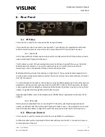
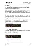
This connector must be connected to rear panel IP Video port either by the supplied short Ethernet
cable if only ASI input mode is required or via a network switch if IP Input mode is required.
6.7.
Eth. 2
This connector is used by the control subsystem for configuring the decoder.
This connector is to be connected directly to the rear panel Ethernet Control port by the supplied
short ethernet cable or, if remote control of the UltraDecoder is required, then the connection must
be made via a network switch.
6.8.
ASI Out
This 75Ω BNC is used to provide an ASI ouput which can be derived from the ASI In signal or ASI over
IP.
6.9.
3G SDI
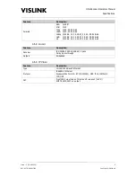
These HD BNCs output 1080P, 1080i, 720P, or SD via industry standard 3G SDI interfaces.
Note that this output is disabled when 4K or Ultra-HD are active.
6.10.
4K HDMI
The HDMI connector outputs 4K (4096 x 2160), 4K Ultra-HD (UHD at 3840 x 2160), HD or SD to
broadcast or consumer displays.
6.11.
AC Power
Power in the range of 90 – 264V AC is connected via 3 pin IEC connector. The total power
consumption is typically less than 100W.
Live and Neutral conductor fusing is employed. The two fuses integrated into the IEC connector
must be ceramic at T5A rating each.
External IEC mains lead must be un-plugged before removal of the lid – dangerous voltages
enclosed.


