background image


Page 27

HDE-264 HD/SD Encoder User and Technical Manual

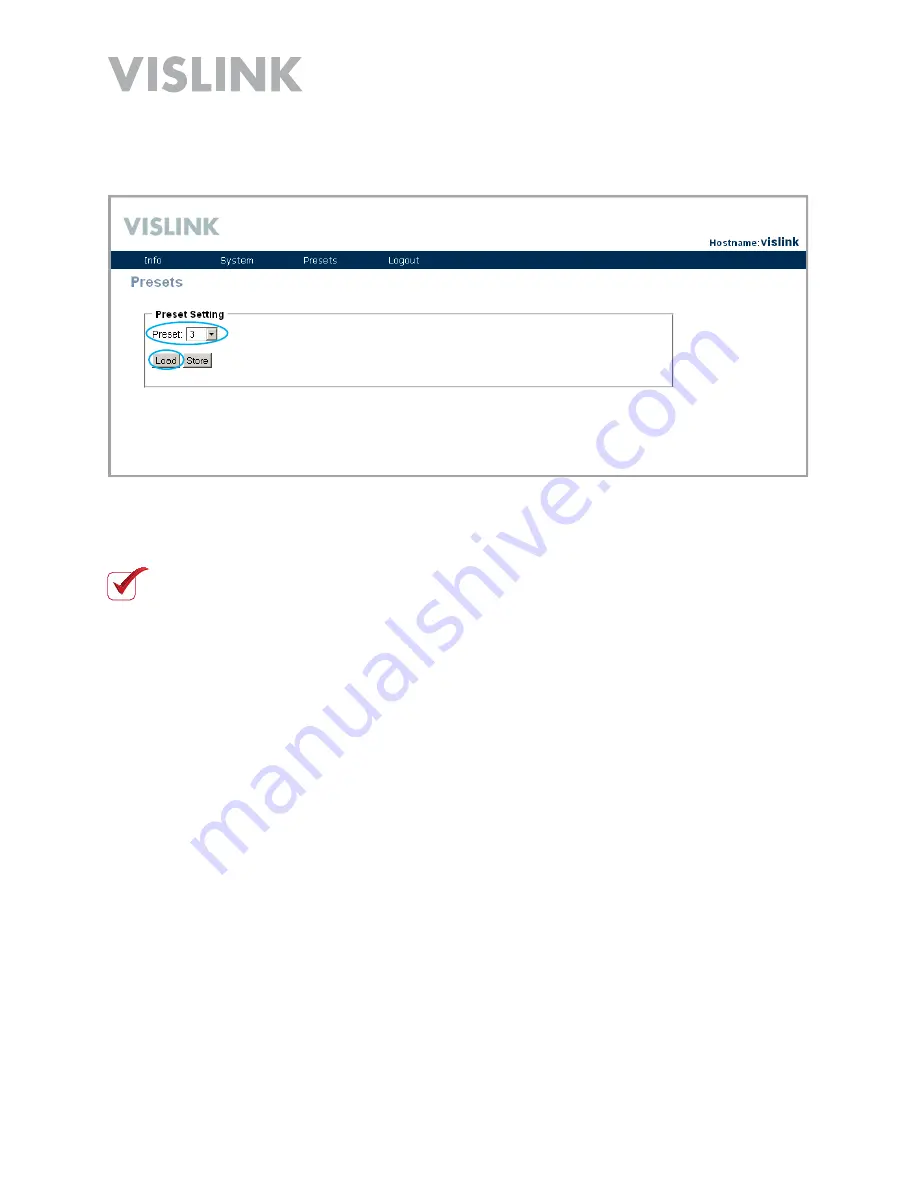
4.  Go to 

Presets > View/Edit

 from the menu bar and on the 

Presets 

screen, click the 

Store

 button to upload the new settings to your encoder 


NOTE

: You 

MUST


Store

 the data on the 

Presets 

screen to upload any changes to 

the encoder.

.  Click the 

Load

 button. The Web Browser Control Interface collects the current data 

from the encoder.

Содержание HDE-264

Страница 1: ...HDE 264 HD SD Encoder User and Technical Manual Manual Part No RD000461 Rev A March 2012 ...

Страница 2: ...e right to make changes to equipment and specifications of the product described in this manual at any time without notice and without obligation to notify any person of such changes General Safety Information The following safety requirements as well as local site requirements and regulations must be observed by personnel operating and maintaining the equipment covered by this manual to ensure aw...

Страница 3: ...le Unit Rack Mount 14 Rack Mount to Portable Unit 14 Portable Unit to Rack Mount 15 Mounting in a 19 Inch Rack 16 Main Control Panel Portable Operation 17 SAVE Button 17 PRESET Button 17 Control Operation Table 18 Audio Input Levels 18 RF Output Power Level 18 Indicator LED Table 19 PC Network Setup 20 Web Browser Control Interface 22 Menu Bar 23 Change Password 23 Factory Settings 24 Streaming ov...

Страница 4: ...Preset Press the front panel UP and Down keys to navigate to the Preset screen Press the Enter key to display the asterisk on the screen Then use the UP and Down keys to navigate to the desired Preset number Press the Enter key to complete the selection Select your desired Video Mode Press the front panel UP and Down keys to navigate to the Video Mode screen Press the Enter key to display the aste...

Страница 5: ...during start up Verify that at least one of your rear panel ASI OUT connectors is connected to a suitable 75 Ohm BNC connector cable and to your destination point transmitter input eg Or if you are streaming IP out to Ethernet ensure that you have a suitable network cable connected to the rear panel RJ 45 Ethernet port and to your destination point PC LAN Port eg Verify that your audio connections...

Страница 6: ...e HDE 264 features high performance MPEG 4 encoding The unit is designed with both ASI and IP outputs Both 1080i and 720p video resolution and a variety of video input interfaces are supported including a unique dual SD encoding format known as Double Vision The HDE 264 Encoder is an ideal cost effective choice for broadcast video distribution live venue events confidence monitoring and video conf...

Страница 7: ... VAC 50 60 Hz and two Fuses 2A 250 V fast blow are located on the rear panel Rack Mount mode Power OFF ON The Power OFF ON is the main power switch while in rack mount operation Power Indicator The Power Indicator lights when AC power is connected and the Power OFF ON switch is set to ON Video Alarm The Video Alarm indicator lights when a valid signal is not present SW Update This USB SW Update co...

Страница 8: ...ual Selecting the Preset Complete the following steps Press the 5 or 6 key The Preset Screen Displays Press the a key Press the 5 or 6 key Press the a key to set 1 2 4 Preset 1 Preset 1 Preset 16 Preset 16 NOTE The asterisk indicates programming mode ...

Страница 9: ...Press the a key Press the 3 4 keys to navigate Press the 5 6 keys to adjust Press the a key to set 1 2 4 5 BitRate Mbps 08 229 BitRate Mbps 08 229 BitRate Mbps 07 229 BitRate Mbps 07 229 NOTE The asterisk indicates programming mode NOTE Valid settings are from 2 Mbps to 15 Mbps only NOTE Setting these parameters will save the changes to the active preset ...

Страница 10: ... the 5 or 6 key The Audio Mode Screen Displays Press the a key Press the 5 6 keys to adjust Press the a key to set 1 2 4 Audio Mode HD SDI Audio Mode HD SDI Audio Mode Analog Audio Mode Analog NOTE The asterisk indicates programming mode NOTE Setting these parameters will save the changes to the active preset ...

Страница 11: ... 5 or 6 key The Video Mode Screen Displays Press the a key Press the 5 6 keys to adjust Press the a key to set 1 2 4 Video Mode 1080i59 94 Video Mode 1080i59 94 Video Mode 720p60 Video Mode 720p60 NOTE The asterisk indicates programming mode NOTE Setting these parameters will save the changes to the active preset ...

Страница 12: ... the rear panel for 600 Ohm balanced input Video In 1 2 BNC Two Video In BNC connectors are located on the rear panel for composite input ASI Out BNC Two ASI Out BNC connectors are located on the rear panel for digital output Ethernet RJ 45 An Ethernet RJ 45 connector is located on the rear panel for Web Browser Control Interface connectivity as well as for streaming IP output ...

Страница 13: ...l Data connector is located on the rear panel of the portable unit and is connected but not visible in rack mounted applications Power 4 Pin Lemo Input Portable Unit Only A 4 Pin Lemo Input DC Power connector is located on the rear panel of the portable unit and is connected but not visible in rack mounted applications RS232 Serial Data DB 9 ...

Страница 14: ...steps Turn OFF power and remove power connection Remove rack mount unit from rack With unit on benchtop losen two captive thumbscrews on the rear panel Slide portable unit until you can access the two cables on the back Carefully remove the Lemo Power pull ferrule and DB 9 serial two captive thumbscrews cables from unit Remove portable unit 1 2 4 5 6 ...

Страница 15: ...t as shown with connectors facing in Connect the DB 9 serial two captive thumbscrews and the Lemo Power pull ferrule cables to the portable unit Slide portable unit in until the screw holes line up with the two captive thumbscrews on the rear panel Carefully place the cables so they are not pinched Tighten the two captive thumbscrews on the rear panel to secure the installation 1 2 4 ...

Страница 16: ...rvice Install the rack mount unit into the 19 inch rack using the optional Extension Bracket Kit as described below Remove either the left or right shown mounting bracket from the HDE 264 by removing the four M6 Philips screws In it s place attach the Extension Bracket using the three 4 40 Philips screws provided Install the unit with the Extension Bracket Kit installed into your 19 inch rack usin...

Страница 17: ...VE Key to complete the task PRESET Button The HDE 264 has up to 16 pre configured PRESETS in memory that include settings such as frequency and power output mode To select a Preset 1 16 complete the following steps Press the PRESET key The currently selected preset LED illuminates Press the Up or Down arrow keys to choose the new preset you want The preset LED illuminates to indicate which preset ...

Страница 18: ...is application Control Operation Table Button Description RF HI LOW N A Move up through presets levels Move down through presets levels AUDIO 1 MIC LINE N A Line only AUDIO 2 MIC LINE N A Line only PRESET Press to enter Preset mode The PRESET LED indicates the current preset Press the UP or DOWN button to select one of the stored Presets 1 16 Press SAVE to confirm the new setting SAVE Confirms the...

Страница 19: ...e as well as ASI or HD SDI digital signal Check the video camera source and cabling to ensure the video signal is reaching the encoder Signal has to match what preset is selected and what is configured in that preset ALARM Red when an alarm occurs Dark when no alarm present Connect encoder to PC via the Ethernet interface to diagnose the source of the alarm CRYPTO Green indicates encryption is ena...

Страница 20: ...rface described in the next section you must first configure your PC as described in the steps given below NOTE Windows 7 is shown here Other versions of Windows may vary slightly From Windows Control Panel go to Network and Sharing Center Click on Change Adapter Settings 1 2 3 Right click the Local Area Connection icon and select Properties The Network Connections window displays ...

Страница 21: ...on 5 The Internet Protocol Version 4 TCP IPv4 Properties dialogue box displays Enter the parameters shown below Next click the OK button This is the proper network setup for connecting to your encoder via the Web Browser Control Interface IP Address 192 168 1 1 Subnet Mask 255 255 255 0 Proceed to the Web Browser Control Interface section NOTE Close the Local Area Connection Properties dialogue bo...

Страница 22: ...r panel of the HDE 264 and to your PC Open a web browser and type default address 192 168 1 200 into the URL address field and press Enter A login screen displays Enter your user name and password then click the Login button NOTE The encoder is factory programmed with the user name root and password root To avoid unauthorized access the factory assigned password should be changed by accessing the ...

Страница 23: ...ord The encoder is factory programmed with the user name root and password root To avoid unauthorized access the factory assigned password should be changed by selecting System Password Change from the menu bar Enter your new password in the New Password field The case sensitive password can be up to 18 characters long numbers and letters only Enter the new password in the Confirm Password field t...

Страница 24: ...ory Settings To access the Factory Settings screen select System Factory Settings on the menu bar The Factory Settings screen is where you can read the Factory Settings directly from your encoder as shown in the Device Mode section of the screen above 123456789 ...

Страница 25: ...sport Stream over Ethernet Settings section bottom portion of the Factory Settings screen You can then view the video stream using a client such as VLC Media Player available for free at http www videolan org vlc NOTE When streaming over IP the Channel Bandwidth setting must be set to TS over Ethernet or RTSP over Ethernet Presets Video Settings Channel Bandwidth 192 168 1 1 Client IP Address must...

Страница 26: ...nual Configuring Presets To configure presets in your encoder complete the following steps To access the Presets screen select Presets View Edit from the menu bar 2 The Presets screen displays Select the desired Preset Setting number to be configured 1 ...

Страница 27: ...e menu bar and on the Presets screen click the Store button to upload the new settings to your encoder NOTE You MUST Store the data on the Presets screen to upload any changes to the encoder 3 Click the Load button The Web Browser Control Interface collects the current data from the encoder ...

Страница 28: ...elect Presets Video Settings from the menu bar near the top of the screen The Encoder Settings screen displays 1 2 Use recommended settings listed in this section appropriate for your application Finally go back to Presets View Edit from the menu bar and on the Presets screen click the Store button to upload the new settings to your encoder NOTE You MUST Store the data on the Presets screen to upl...

Страница 29: ...0i Frame Rate Match Input Output TS over Ethernet Scale Factor No Scaling H 264 Profile High Slices 1 Slice per Frame GOP Length 15 Standard Definition Low Delay Video Settings Input A Composite Input B Disabled Resolution 480i Frame Rate Match Input Output TS over Ethernet Scale Factor No Scaling H 264 Profile High Slices 1 Slice per Frame GOP Length 0 ...

Страница 30: ...rame Rate Match Input Output TS over Ethernet Scale Factor No Scaling H 264 Profile High Slices 1 Slice per Frame GOP Length 0 High Definition Normal Delay Video Settings Input A SDI Input B Disabled Resolution 1080i Frame Rate Match Input Output TS over Ethernet Scale Factor No Scaling H 264 Profile High Slices 1 Slice per Frame GOP Length 30 ...

Страница 31: ...io Settings Mode Analog Analog Input Line Sample Rate 48 kHz Encoding Mode MPEG 2 Mic Gain Left 0 Mic Gain Right 0 Embedded Audio Audio Settings Mode SDI Analog Input Line Sample Rate 48 kHz Encoding Mode MPEG 2 Mic Gain Left 0 Mic Gain Right 0 Microphone Audio Not available ...

Страница 32: ...u bar The Board Information screen shows the Status section including the RF channel Bandwidth and the Encoder Target Bitrate The throughput indicated here can sometimes be useful in troubleshooting should a problem occur The Board Information section is also displayed which may provide useful specifics about your encoder to Customer Service ...

Страница 33: ... the menu bar The Firmware Upgrade screen displays Click the Browse button on the Firmware Upgrade screen and navigate to the firmware image Select the firmware image file then click on the UPGRADE button to start the firmware upgrade NOTE Do not disconnect power during the upgrade process It can take several minutes to complete the upgrade process Click Continue when prompted When the upgrade is ...

Страница 34: ...20 PAL 352 x 704 PAL HD 1080i 50 59 60 1080p 50 60 720p 50 60 Video IP Interfaces Input HD SDI SD SDI CV Conn 1 x BNC F HD SD 1 x BNC F SD Output 2 x ASI 75Ω EN50083 9 Data Rate Up to 15 Mbps Conn 2 x BNC F ASI Output 1 x IP 802 11 Type UDP streaming Multicast future Conn 1 x RJ45 IP Audio Input Interfaces Analog SD SDI HD SDI embedded Channel Support 1 x Stereo Pair Impedance 4 dBm 600Ω balanced ...

Страница 35: ... 16 User selectable Physical and Power Input Voltages 105 VAC 260 VAC 50 60 Hz rack mount 22 to 32 VDC portable unit On Off Switch Front Panel Power Dissipation 18W Chassis 209 x 182 x 44 mm WxDxH Rack Unit in 19 1RU rack space Installation 19 1 RU rack mounting kit Environmental Conditions Operating Temperature 10 C to 50 C Storage Temperature 20 C to 70 C Relative Humidity 5 to 95 non condensing...

Страница 36: ...Page 36 HDE 264 HD SD Encoder User and Technical Manual Notes ...

Страница 37: ...or 888 777 9221 In the US or Canada When you contact T echnical Support include the following information Model number and serial number of the unit located on a label on the bottom of each unit Approximate purchase date There are no supported field repairs for this product Return the unit for factory repair NOTE If you attempt field repair you risk damaging your equipment If your equipment is und...

Страница 38: ...HDE 264 HD SD Encoder User and Technical Manual ...

Отзывы: