background image

Wiring 

Wire Color 

Function 

                              Notes 

Basic Stand Alone Wiring 

Red 

12-24V AC/ DC 

12-24V AC/DC Regulated Power Input 

Black 

GND 

Negative Pole of DC Power Input 

Pink 

12-24V AC 

12-24V AC Regulated Power Input 

Blue 

Relay NO 

Normally Open Relay Output (install diode provided) 

Purple 

Relay Common 

Common Connection for Relay Output 

Orange 

Relay NC 

Normally Closed Relay Output (Install diode provided) 

Yellow 

OPEN 

Request to Exit (REX) Input 

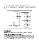
Pass-Through Wiring (Wiegand Reader) 

Green 

Data 0 

Wiegand Output (Pass-through) Data 0 

White 

Data 1 

Wiegand Output (Pass-through) Data 1 

Advanced Input and Output Features 

Grey 

Alarm Output 

Negative contact for Alarm 

Brown 

Contact Input 

Door/Gate Contact Input (Normally Closed) 


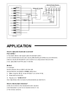
Connection Diagram   

DC Power Supply: 


Содержание VIS-3009

Страница 1: ...Access Control Black Outdoor IP66 Weatherproof Card Reader Standalone No Software Wiegand 26 37 Bits 125KHz EM Cards 1 000 Users VIS 3009 User Manual...

Страница 2: ...ed With Wiegand 26 37 input output Pulse mode Latch mode Card block enrolment Tri colour LED status display Built in light dependent resistor LDR for anti tamper Integrated Alarm Buzzer Output Low tem...

Страница 3: ...Drill 2 holes A C on the wall for the screws and one hole for the cable Knock the supplied rubber bungs to the screw holes A C Fix the back cover firmly on the wall with 4 flat head screws Thread the...

Страница 4: ...rple Relay Common Common Connection for Relay Output Orange Relay NC Normally Closed Relay Output Install diode provided Yellow OPEN Request to Exit REX Input Pass Through Wiring Wiegand Reader Green...

Страница 5: ...AC Power Supply Attention Install a 1N4004 or equivalent diode is needed when use a common power supply or the reader might be damaged 1N4004 is included in the packing Access Control Power Supply...

Страница 6: ...d Any 125KHz industry standard 26 bit EM Proximity card Enter and Exit Program mode Set Master Code Programming Step Keystroke Combination 1 Enter Program Mode Master Code 2 Update Master Code 0 New M...

Страница 7: ...ode 2 Delete User By User ID OR 2 Delete User By Card OR 2 Delete User By Card number OR 2 Delete All User 2 User ID 2 Read Card 2 Input 8 10 digits Card number 2 Mater Code 3 Exit Set Relay Configura...

Страница 8: ...Keystroke Combination 1 Enter Program Mode Master Code 2 Control Sounds OR 2 Control LED OFF 7 0 OFF 7 4 ON 7 1 ON 7 5 Factory defaults are ON 3 Exit Users Operation Open the door Read the valid user...

Страница 9: ...Code 2 Interlocked OFF OR 2 Interlocked ON 9 0 Factory default 9 1 3 Exit Connection diagram see picture Interlock at page 13 Set Card Reading Type Programming Step Keystroke Combination 1 Enter Progr...

Страница 10: ...transmit the card number the 10 digits number on the card when it reads the Card Controller Mode VIS 3009 operating as a Controller VIS 3009 supports a Wiegand 26 37 bit input so an external Wiegand...

Страница 11: ...oad download 1000 users in 3 minutes Method For example Device A Master code is 222222 with User data Device B Master code MUST be 123456 without User 1 Make connection D0 A connect D0 B D1 A connect...

Страница 12: ...ming mode 123456 then you can do the programming 123456 is the default factory master code change the master code 0 new code repeat the new code code 6 digits Add card user 1 Read Card can add Cards c...

Отзывы: