- Page 2 -
Installation Instructions
©2005-2018
Vision3 Lighting
™ P.O. Box 607, Fowler, CA 93625 (559) 834-5749 (559) 834-4779 fax www.vision3lighting.com
revision 5/16/18
INSTRUCTIONS PERTAINING TO A RISK OF FIRE, OR INJURY TO PERSONS.
IMPORTANT SAFETY INSTRUCTIONS. SAVE THESE INSTRUCTIONS.
(Failure to follow the warnings and instructions on this sheet could result in fire, injury, failure of product, and/or voiding of warranty.)
MR16 Bollard Path Light
MODEL PA7
12V 7.5W, 12/24V 10W, or 12V 12.5W LED
12V 50W Max., MR16 Halogen
supplied) to the surface of the Heatsink that will contact the bottom
of the LED Module.
f.
Align the pins on the LED Module with the socket and push straight
in. Do not twist or push in at an angle or the pins may be damaged.
g.
Install and tighten the LED Module Screws.
Caution!
Over
tightening of screws could crack the LED Module case.
For Retrofit MR16 LED Lamp:
a. Pull lamp straight out.
Caution! Lamp may still be hot!
Be sure
lamp has cooled before touching.
b. Inspect socket for any damage.
c.
Clean inside of fixture and Cap with a clean dry cloth.
d.
Push new lamp straight in, being careful to align pins. Make sure
Retrofit MR16 Lamp fully contacts Heatsink Mount, otherwise
lamp may overheat and fail prematurely.
Note:
Replacement lamp
must not exceed ratings on Label. Only use Vision3 approved
Retrofit MR16 Lamp and supplied Heatsink Mount, otherwise LED
may overheat and fail.
7.
Re-install Socket Mount Assembly in to Faceplate Assembly.
8.
Tighten Faceplate Set Screw with the 3/32” hex tool so that is just
bottoms out.
9.
Insert the Faceplate Assembly in to the Body. Note: Make sure the wiring
is not kinked or pinched in any way.
10.
Use the Faceplate Screws (2X) to attach the Faceplate Assembly to the
Body. Notes: Skip the next steps if your fixture does not have a cover
option:
11. Slide the Cover over the Faceplate as far as it will go, and properly orient.
Note: Eyelid should not be pointed up as it will fill with water and debris.
12. Gently tighten each Cover Set Screw against Faceplate.
LED Switching (on certain models):
1. Remove the Faceplate
Assembly to gain access to
the Integral LED Module
as explained in Lamp
Maintenance steps 1 thru 5.
2. Inspect for damage. Replace
any damaged parts, if
necessary.
3.
Clean inside of fixture with a
clean, damp cotton cloth.
4.
Find LED High/Low Switch on side of Integral LED Module.
5.
Using a pin, small nail, etc, flip the switch in the desired direction. See
the LED Module Switch sketch for which direction corresponds to which
setting.
6.
Re-assemble as explained in Lamp Maintenance steps 7 thru 12.
Accessory Maintenance:
1.
Remove the Faceplate Assembly to gain access to the accessories, as
explained in Lamp Maintenance steps 1 thru 5
.
2. Remove Accessory Clip from Cap.
3. Carefully remove Accessories from Cap, if any.
4. Inspect Cap, Accessories, and Clip for damage. Replace if necessary.
5. Clean Cap and Accessories with a clean, damp cotton cloth.
6. Carefully install new Accessories into Cap (Cap may hold up to 2
Accessories).
7. Compress Clip and push into Cap until it holds Accessories tightly in
Cap.
8.
Re-assemble as explained in Lamp Maintenance steps 7 thru 12
.
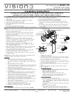
LED Module Switch
Low
High
Integral LED Module
LED High/Low Switch
PA7 Heatsink


