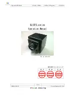
Operation Manual
Check Y.Mito
Author F.Ogawa
2012/7/2
1/19
.
SPD-1207001
V
i
s
on Sens
ng Co. Ltd
ULVIPS series
For up to Ver3.0
株式会社ビジョンセンシング
検
印
照
査
作
成
Visio n
2 0 1 0 / 1 1 / 2 4
水戸
Se n sin g
V i s i on
2010/11/24
大久保
Sens i ng
嵯 峨
Страница 1: ...ito Author F Ogawa 2012 7 2 1 19 SPD 1207001 Vision Sensing Co Ltd ULVIPS series Operation Manual For up to Ver3 0 株式会社ビジョンセンシング 検 印 照 査 作 成 Vision 2010 11 24 水戸 Sensing Vision 2010 11 24 大久保 Sensing Vision 2010 11 24 嵯峨 Sensing ...
Страница 2: ... outside control pulsed output pin 4 3 About a trigger input pin outside the 4 3 and the outside control pulsed output pin 4 3 About a trigger input pin outside the 4 3 and the outside control pulsed output pin 4 3 About a trigger input pin outside the 4 3 and the outside control pulsed output pin 9 4 4 Camera connecting 4 4 Camera connecting 4 4 Camera connecting 4 4 Camera connecting 10 4 5 Came...
Страница 3: ...more than 3 0 it s necessary to do an update CameraVervion3 0 and a written sticker are stuck on an applied camera CameraVervion3 0 and a written sticker are stuck on an applied camera CameraVervion3 0 and a written sticker are stuck on an applied camera CameraVervion3 0 and a written sticker are stuck on an applied camera 2 2 2 2 ULVIPS ULVIPS ULVIPS ULVIPS camera overview camera overview camera ...
Страница 4: ...ut k Output Pixel clock 48MHz Image bit size Maximum 14bits Maximum frame rate UL03 162 262 50fps UL02 152 60fps UL04 171 60fps UL04 272 50fps UL05 251 60fps Cameralink Signal Format It is synchronized with FVAL of the cameralink standard and send a frame of picture It is synchronized with LVAL and send a line of picture DVAL isn t used Applied grabber board DALSA X64 CL X64 CL iPro X64 Xcelera CL...
Страница 5: ...hen doing picture confirmation in Sapera Cam Export please use the following camera setting file ccf UL02 152 ULVIPS02152 ccf UL03 162 262 ULVIPS03162 ccf UL04 171 ULVIPS04171 ccf UL04 272 ULVIPS04272 ccf UL05 251 ULVIPS05251 ccf These files are in Installation CD 2 USB Output 2 USB Output 2 USB Output 2 USB Output It s possible to get image through USB It corresponds to only this application The ...
Страница 6: ...t cut cut When exchanging the kind of sensors all set values which were being When exchanging the kind of sensors all set values which were being When exchanging the kind of sensors all set values which were being When exchanging the kind of sensors all set values which were being preserved inside the camera return to defaults preserved inside the camera return to defaults preserved inside the cam...
Страница 7: ...era connector connector connector connector 4 1 Connector location 4 1 Connector location 4 1 Connector location 4 1 Connector location mini CameraLink mini CameraLink mini CameraLink mini CameraLink Connector Connector Connector Connector LED LED LED LED Power C Power C Power C Power Connector onnector onnector onnector BNC BNC BNC BNC Connector Connector Connector Connector USB USB USB USB Conne...
Страница 8: ...ink output a camera link cable is connected to this connector A connector of the power connector Power supply and DIO connector Input Voltage 9 16V Fitness connector HR10A 10P 12P HIROSE Pin out will be as follows 10 11 12 5 9 3 1 6 4 7 2 8 GND VCC IN0_COMMON IN0 IN1_COMMON IN1 OUT1_COMMON OUT1 OUT0 OUT0_COMMON Power supply connector pin assign VCC 12V Power supply GND Grand IN0 External camera tr...
Страница 9: ...tside control pulsed output pin External trigger input equivalent circuit photo coupler PS2805 4 NEC Please usually make the pulse of 5V course an input signal External digital output equivalent circuit photo coupler PS2805 4 NEC Be careful for electrical polarity Camera inside OUT 0 or OUT 1 OUT 0 COMMON or OUT 1 COMMON Internal output PS2805 4 NEC ...
Страница 10: ...Link Image out Power supply 9 16V Grabber board PC1 PC2 USB Image out and cam control Don t connect both interface It s possible to go out image from one side The length of USB cable is less than 5m The length of USB cable is less than 5m The length of USB cable is less than 5m The length of USB cable is less than 5m 4 5 Camera connecting when using external trigger and digital output Caution ...
Страница 11: ...view Display overview Display overview Image display Image display Image display Image display Display image from camera Camera control dialog Camera control dialog Camera control dialog Camera control dialog Control for camera setting Dynamics range Dynamics range Dynamics range Dynamics range A dynamics processing mode is performed in the PC to an input picture from a camera Color Mono Color Mon...
Страница 12: ...ble in the camera ly a table more than one when existing it s possible to change to designated table name It s changed automatically the scale of color table 5 2 Capturing image When acquiring a picture please click picture acquisition starting Tree peony the part surrounded with the above red When it isn t during picture acquisition a dynamics processing mode can t be controlled Color image in ca...
Страница 13: ...he part surrounded with the above red and choose a table When changing a table a color bar on the temperature table is switched over automatically 5 4 Measurement temperature range Temperature range Show temperature range current setting Offset value A difference in the temperature by the cause of the distance is revised Emissivity Set the emissivity value according to target object Typical materi...
Страница 14: ...Operation Manual Check Y Mito Author F Ogawa 2012 7 2 14 19 SPD 1207001 Vision Sensing Co Ltd Target object Emissivity Skin 0 98 Paper 0 93 Polished steel 0 07 0 11 Glass 0 95 ...
Страница 15: ...splay window 5 Display window 5 Display window The coordinate when a frame rate mouse pointer stopped is indicated under the screen A frame rate fluctuates by a specification of a PC Change the display window size When a QVGA size VGA size screen maximum display setup button is chosen from a size setup button I switch over ...
Страница 16: ...point clear The item chosen in the sampling coordinate spot indication area is eliminated All clear All clear All clear All clear The item shown to a sampling coordinate spot indication area at present is eliminated completely Sampling condition setting Sampling condition setting Sampling condition setting Sampling condition setting The setting to do sampling image sampling of a choice coordinate ...
Страница 17: ...time Sampling time is set 1 1440 minutes The destination folder name for saving The destination folder name for saving The destination folder name for saving The destination folder name for saving The place where a picture and a csv file are stocked as a result of the time when a picture and fixed point brightness sampling were performed is set When starting it s set as My Document Start sampling ...
Страница 18: ...hor F Ogawa 2012 7 2 18 19 SPD 1207001 Vision Sensing Co Ltd 5 7 Save current display image When I name from file Tree peony in the upper right and click preservation the current display image can be preserved by the designation format ...
Страница 19: ...Operation Manual Check Y Mito Author F Ogawa 2012 7 2 19 19 SPD 1207001 Vision Sensing Co Ltd Update records No Item Date Author 1 First edition Ref JPN edit No 12 2012 7 1 F Ogawa ...