p.6
STEP 5
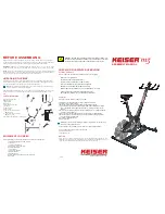
Plug the button connectors(17) into the
brain box(6) as shown. Open the bat-
tery compartment on the brain box(6)
by pressing in on the sides until the
tabs slide easily out. Install 2 AA batter-
ies as shown (batteries not included).
Replace the battery cover.
STEP 6
The pedals(15 & 16) are marked “L”
and “R” - Left and Right. Connect
them to their corresponding crank
arms. Note that the right pedal will
be threaded on clockwise, but the
left pedal will be threaded on count-
er-clockwise. This is so that the
pedals will not loosen themselves
as you pedal.
If desired attach the pedal straps
to the pedals using the tabs on the
sides on the pedals.
Hardware Assembly is complete! If
you haven’t yet read the important
safety information on page 1, this
would be a good time to do so.
17
6
15
16
Содержание VZ-EA1
Страница 1: ...VZ EA1 Product Manual...
Страница 2: ......
Страница 4: ...p 2 2 2 1 3 6 7 9 17 10 12 18 11 19 20 29 13 14 15 30 16 21 20 29 22 20 29 21 8 5 23 24 26 4...
Страница 10: ...p 8...
Страница 11: ...p 9...
Страница 12: ...p 10...


