4
1 .
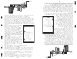
L ’illustration de la page 4 présente une configuration t
ypique d’installation du
système d’eau pot
able et des composants connexes qui peu
vent être utilisés
lors de l’installation. On recommande l’inst
allation d’un circuit de dérivation,
ce qui permettra l’e
xécution d’inter
ventions d’entretien sans inter
ruption
de la distribution d’eau. Dans un tel cas, on doit noter qu’une opération de
désinfection additionnelle du circuit de distribution sera nécessaire si de l’eau
non désinfectée y a circulé. De plus, l’eau qui circulerait dans le sy
stème à
travers le circuit de dériv
ation NE SERAIT P
AS désinf
ectée – on doit donc
installer bien en vue l’étiquet
te fournie
“NE PAS CONSOMMER L
’EAU”
sur
le circuit de dérivation jusqu’à ce que le traitement de désinf
ection complet du
système ait été ef
fect
ué et qu’il ait été remis en
service.
Voir la description complète du processus
de désinfection à la page 6 de ce document. Si
de l’eau qui n’a pas été traitée par le sy
stème (à
l’occasion d’une intervention d’entretien) doit être
consommée, on doit la faire bouillir vingt minutes
avant de la consommer
.
2.
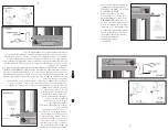
Choisir un emplacement approprié pour
l’installation du sy
stème de désinfection et
des composants connexes.
Tenir compte de la
recommandation d’installer un disjoncteur de
fuite à la terre (recommandé). L
ors du choix
de l’endroit pour installer l’appareil, pré
voir
suffisamment d’espace pour permet
tre le retrait
de la lampe UV/du manchon en quartz.
Vous
devez aussi a
voir l’espace nécessaire pour
changer les filtres cartouc
hes, soit un espace
équivalent à l’espace qu’occupe la c
hambre
du réacteur, au-dessus et en dessous (v
oir la
Figure 1A).
(Note : pour fins de démonstration seulement, ces diagrammes
représentent une installation comprenant le sy
stème Cobalt“PLUS” avec un
capteur UV)
3.
Fixer le sy
stème au mur à l’aide des tire-fonds appropriés (non f
ournis) aux trous
de montage du support mét
allique. Afin de maintenir le débit maximal spécifi
é
par les fabricants, nous recommandons f
ortement l’utilisation d’un limitateur de
débit lors de l’installation du sy
stème. On doit installer le limiteur de débit sur la
sortie d’eau, tout en respectant le sens de circulation de l’eau (fl
èche gra
vée sur
le régulateur de débit – Figure 1C). N’EFFECTUER
AUCUNE OPÉRA
TION DE
SOUD
AGE PEND
ANT QUE LES RACCORDS SONT FIXÉS
AU S
YSTÈME
VO
US
POUVEZ CA
USER DES DOMMA
GES AUX J
OINTS TORIQUES
.
4.
Afin de prévenir une possible infiltration d’eau dans le contrôleur
, faire une
boucle d’égouttement au cordon d’aliment
ation et au capteur (série SCM) et
4
this manual. If the water is to be consumed while the system is off-line, the
water must be boiled for twenty minutes prior to consumption.
2. Select a suitable location for the disinfection system and its related
components. As it is recommended to install a ground fault protected circuit
(GFCI), make sure that this is taken into consideration prior to any installation.
When selecting a mounting location, you must leave enough space to allow
for the removal of the UV lamp/quartz sleeve, as well as enough space to
change out the filter cartridges (typically leave a space equal to the size of the
reactor chamber itself above and approximately 4 inches below for the filters)
(Figure 1A).
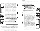
3. Mount the system to the wall with appropriate
lag bolts (not supplied) through the two
mounting holes located on the metal bracket.
The flow restrictor should be installed on the
outlet port and is designed to be installed in
one direction only. Ensure that the flow of the
water matches the flow direction as indicated
on the flow restrictor (Figure 1B). DO NOT
SOLDER CONNECTIONS WHILE ATTACHED TO
THE SYSTEM AS THIS COULD DAMAGE THE
O-RING SEALS.
4. Make sure you allow for a “drip-loop” on the
power cord and sensor to prevent any water
from potentially entering the controller. Run
lamp and sensor cord under ballast, to prevent
water from potentially entering the controller
(Figure 1C). Affix the green ground wire to the
grounding lug at the top of the reactor vessel
and securely fasten with the lock nut provided
(Figure 1D).
5. Install the UV lamp and UV sensor as outlined on pages 7-9.
6. Install the cartridges as outlined on page 10.
7. When all plumbing connections are made, slowly turn on the water supply
and check for leaks. The most likely cause for leaks is from o-ring seals. In
case of a leak at the reactor, shut water off, remove the retaining nut, wipe
the o-ring and threads clean and re-install. In case of a leak at the filters,
remove the sump, wipe the o-ring and threads clean, ensure the o-ring is
fitted properly, then reinstall.
8. Once it is determined that there are no leaks, plug the system into the
ground fault circuit interrupter (GFCI), and check controller to ensure the
system is operating properly. The controller is designed to detect both
Содержание Sterilight PLATINUM SPV410-IHS22
Страница 2: ......


