background image

1

12

2

© 2005 Directed Electronics—all rights reserved

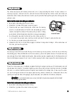
3. Start and run the vehicle. 

4. Probe the wire you suspect of being the tachometer wire with the red probe of the meter.

5. If this is the correct wire the meter will read between 1V and 6V.

In diesel vehicles it is necessary to interface with the wire that turns on the WAIT TO START light in the dash-

board. This wire illuminates the bulb until the vehicle’s glow plugs are properly heated. When the light goes out

the vehicle can be started. This wire is always available at the connector leading to the bulb in the dashboard.

It can also be found at the Engine Control Module (ECM) in many vehicles. 

TTo

o  tteesstt  aan

nd

d  d

deetteerrm

miin

nee  tth

hee  p

po

ollaarriittyy  o

off  tth

hiiss  w

wiirree::

1. Set your multimeter to DCV or DC voltage (12 or 20V is fine).

2. Attach the (+) probe of the meter to (+)12V.

3. Probe the wire that you suspect leads to the bulb with the (-) probe of the meter.

4. Turn the ignition switch to the ON position.

5. If the meter indicates 12 volts until the light goes out you have isolated the correct wire and the wire's polar-

ity is negative (ground while the bulb is on).

6. If the meter reads zero volts until the light goes out and then reads 12 volts, you have isolated the correct

wire and the wire's polarity is positive.

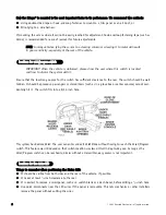
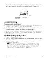
The (+) parking light wire is often found near the switch. Many cars have the switch built into the turn signal

lever, and in these cars the parking light wire can be found in the steering column. The same wire is often avail-

able in the kick panel or running board.

N

NO

OTTEE::  Many Toyotas, as well as many other Asian vehicles, send a (-) signal from the switch to

a relay. The relay then sends (+)12V to the bulbs. Whenever you have difficulty finding a (+)
parking light wire near the switch, simply test the wires at any switch or control panel which is
lit by the instrument panel lighting. Remember, you need a (+) parking light wire that does not
vary with the dimmer setting.

H

Ho

ow

w  tto

o  ffiin

nd

d  aa  ((+

+))  p

paarrkkiin

ng

g  lliig

gh

htt  ffllaassh

h  w

wiirree  w

wiitth

h  yyo

ou

urr  m

mu

ullttiim

meetteerr::

1. Set to DCV or DC voltage (12V or 20V is fine).

2. Attach the (-) probe of the meter to chassis ground.

3. Probe the wire you suspect of being the parking light wire. Usually, the area near the headlight/parking light

switch is an excellent area to start, as is the kick panel. 

4. Turn on the parking lights. If your meter shows (+)12V, turn off the parking lights and make sure it goes back

to zero.

5. If it does return to zero, turn the parking lights back on and, using the dash light dimmer control, turn the

ffiinnddiinngg  aa  ((++))  ppaarrkkiinngg  lliigghhtt  w

wiirree

ffiinnddiinngg  tthhee  w

waaiitt--ttoo--ssttaarrtt  bbuullbb  w

wiirree  ffoorr  ddiieesseellss  

Содержание 771XV

Страница 1: ...stallation by a professional installer only Any attempt to install this product by any person other than a trained professional may result in severe damage to a vehicle s electrical system and compone...

Страница 2: ...Warn Away are all Trademarks or Registered Trademarks of Directed Electronics N Ne ew w S So of ft tw wa ar re e C Co om mp pa at ti ib bi il li it ty y f fo or r 1 10 03 3T T K Ke ey yp pa ad d This...

Страница 3: ...on harness 25 auxiliary relay output harness 25 r re em mo ot te e s st ta ar rt t s se ec co on nd da ar ry y h ha ar rn ne es ss s H H3 3 w wi ir re e c co on nn ne ec ct ti io on n g gu ui id de e...

Страница 4: ...system does not unintentionally remote start the vehicle 4 T TH HE E U US SE ER R M MU US ST T I IN NS ST TA AL LL L A A C CA AR RB BO ON N M MO ON NO OX XI ID DE E D DE ET TE EC CT TO OR R I IN N O O...

Страница 5: ...oiin nt ts s t to o r re em me em mb be er r I IM MP PO OR RT TA AN NT T This product is designed for fuel injected automatic transmission vehicles only Installing it in a standard transmission vehicl...

Страница 6: ...om as the factory When possible place the siren on the same side of the vehicle as the control module where its wires will reach the control module s wires without extending them Always run the wires...

Страница 7: ...ing area with a quality glass cleaner or alcohol to remove any dirt or residue 3 Mount the antenna using the supplied double sided tape 4 Route the antenna cable to the control module and plug it into...

Страница 8: ...tch should be well hidden It should be placed so passengers or stored items such as in a glove box or center console cannot acci dentally hit it The switch fits into a 9 32 inch hole This system has R...

Страница 9: ...imum length necessary Since the relay satellite is functioning as the ignition switch in the vehicle it is often convenient to mount the relay satellite close to the main ignition switch harness f fii...

Страница 10: ...sory wires lose power when the key is in the start position to make more current available to the starter motor H Ho ow w t to o f fi in nd d 1 12 2V V i ig gn ni it ti io on n w wi it th h y yo ou ur...

Страница 11: ...cessory and run positions It will not show 12V during the cranking cycle There will often be more than one accessory wire in the ignition harness The correct accessory wire will power the vehicle s cl...

Страница 12: ...The parking light wire is often found near the switch Many cars have the switch built into the turn signal lever and in these cars the parking light wire can be found in the steering column The same...

Страница 13: ...n an easy location is not available running a wire to the dome light itself is often the best solution H Ho ow w t to o f fi in nd d a a d do oo or r p pi in n s sw wi it tc ch h t tr ri ig gg ge er r...

Страница 14: ...g a wire connection solder connections and crimp connectors When properly performed either type of connection is reliable and trouble free Regardless of whether you solder your connections or you use...

Страница 15: ...E ED D W WH HI IT TE E 2 20 00 0 m mA A C CH HA AN NN NE EL L 2 2 V VA AL LI ID DI IT TY Y O OU UT TP PU UT T R RE ED D C CO ON NS ST TA AN NT T P PO OW WE ER R I IN NP PU UT T B BR RO OW WN N S SI IR...

Страница 16: ...T P PU UR RP PL LE E 2 20 00 0 m mA A S ST TA AR RT TE ER R R RE EL LA AY Y T TU UR RN N O ON N O OR RA AN NG GE E 2 20 00 0 m mA A A AC CC CE ES SS SO OR RY Y R RE EL LA AY Y T TU UR RN N O ON N P P...

Страница 17: ...GR RA AY Y H HO OO OD D P PI IN NS SW WI IT TC CH H I IN NP PU UT T Z ZO ON NE E 1 1 B BL LU UE E W WH HI IT TE E 2 20 00 0 m mA A 2 2N ND D S ST TA AT TU US S R RE EA AR R D DE EF FO OG GG GE ER R L...

Страница 18: ...his wire supplies a 200 mA output This is suitable for driving light control wires in Toyota Lexus BMW some Mitsubishi some Mazda and other model cars P Po os si it ti iv ve e L Li ig gh ht t F Fl la...

Страница 19: ...relay as shown below I IM MP PO OR RT TA AN NT T This output is only intended to drive a relay It cannot be connected directly to the domelight circuit as the output cannot support the current draw o...

Страница 20: ...clean paint free sheet metal location driver kick panel using a factory bolt that DOES NOT have any vehicle component grounds attached to it A screw should only be used when in conjunction with a two...

Страница 21: ...the system receives the code controlling Channel 2 for longer than 1 5 seconds the red white wire will supply an output as long as the transmission continues This is often used to operate a trunk hatc...

Страница 22: ...the wire in the vehicle that sends the signal to turn on the WAIT TO START bulb in the dash board In most diesels the wire is negative ground turns on the bulb and the GRAY BLACK wire can be directly...

Страница 23: ...ved L La at tc ch he ed d Output that will send a signal when the Channel 4 button s is pressed and will continue until the same button s is pressed again L La at tc ch he ed d r re es se et t w wi it...

Страница 24: ...doors when installing progressive door locks for instance r re ella ay y s sa at te elllliit te e iig gn niit tiio on n s sw wiit tc ch h iin nt te er rf fa ac ce e w wiir re e c co on nn ne ec ct ti...

Страница 25: ...vehicles that do not have a second ignition wire this connection is not required The ribbon harness connects from the control module The 4 pin harness provides the capability of driving additional re...

Страница 26: ...security system if the hood is opened while the system is armed and report Zone 6 This wire MUST be connected to the vehicle s brake light wire This is the wire that shows 12V when the brake pedal is...

Страница 27: ...vehicle from accidentally being started while in a drive gear This input MUST rest at ground in order for the remote start system to operate Connected properly the vehicle will only start while in PA...

Страница 28: ...lly interrupts the starter wire is used when the vehicle is in any drive gear If the remote start is inter faced before this switch it will provide protection from starting in gear However some vehicl...

Страница 29: ...a General Motors product or a Dodge Dakota pickup please call Directed Electronics Technical Support for an alternative shut down method Do not return the vehicle to the customer until this feature is...

Страница 30: ...MP PO OR RT TA AN NT T Once the interface is complete attempt to remote start the vehicle with the door closed and the key in the ignition The vehicle should not start If it does recheck the connectio...

Страница 31: ...ght gauge wires coming out of the steering column The colors of the wires vary but they are often contained in orange tubing either both will be white wires or one wire will be purple white and the ot...

Страница 32: ...dition Passlock systems require seeing the correct R code at the correct time To bypass Passlock I and II p p n n 5 55 55 5L L is required The Passkey III system can be found in the following vehicles...

Страница 33: ...o pin socket while the Valet Program Switch should be plugged into the larger blue two pin connector The Status LED fits into a 9 32 inch hole N NO OT TE E Never use a BLUE LED in combination with a R...

Страница 34: ...st ta ag ge e s se en ns so or r t to o g gr re ee en n w wi ir re e Z Zo on ne e 2 2 Inputs shorter than 0 8 seconds will trigger the Warn Away response while inputs longer than 0 8 seconds will tri...

Страница 35: ...r rn n t th he e t ta ac ch h s si ig gn na al l 1 Start the vehicle with the key 2 Within 5 seconds press and H HO OL LD D the Valet Program switch 3 The LED will light constant when the tach signal...

Страница 36: ...be used on the H1 2 light flash output harness wire t tr ra an ns sm miit tt te er r r re ec ce eiiv ve er r lle ea ar rn n r ro ou ut tiin ne e The system comes with one transmitter that has been tau...

Страница 37: ...n transmitters from the system s memory It can also be used to start from scratch if the transmitter buttons were programmed incorrectly 4 P Pr re es ss s t th he e t tr ra an ns sm mi it tt te er r b...

Страница 38: ...Door is closed Valet Program button is pressed too many times More than 15 seconds elapses between steps One long chirp indicates that Learn Routine has been exited t tr ra an ns sm miit tt te er r c...

Страница 39: ...witch However this process can be greatly simplified by using the Bitwriter Any of the settings can be changed and then assigned to one of up to four transmitters This feature is called Owner Recognit...

Страница 40: ...feature press and release 3 times Then press the button once more and H HO OL LD D it The siren will chirp the number of times equal to the feature you have accessed 5 P Pr ro og gr ra am m t th he e...

Страница 41: ...rp indicating which menu has been accessed For example if you just programmed some features in the first menu and you want to program a feature in the third menu press and H HO OL LD D the Valet Progr...

Страница 42: ...i ic c w wi it th h i ig gn ni it ti io on n o on n No panic with ignition on 1 7 0 0 8 8 s se ec co on nd d d do oo or r l lo oc ck k p pu ul ls se es s 1 3 5 2 0 4 3 seconds 1 8 F Fo or rc ce ed d p...

Страница 43: ...Unlock output 2 pulses 2 8 L Lo oc ck k o ou ut tp pu ut t 1 1 p pu ul ls se e Lock output 2 pulses 2 9 F Fa ac ct to or ry y d di is sa ar rm m w wi it th h C Ch ha an nn ne el l T Tw wo o O ON N Fa...

Страница 44: ...in n 1 3 2 5 3 10 4 min 3 8 Activation pulse count 1 A Ac ct ti iv va at ti io on n p pu ul ls se e c co ou un nt t 2 2 3 9 2 2n nd d I Ig gn ni it ti io on n A Ac cc c o ou ut tp pu ut t i ig gn ni...

Страница 45: ...en the system can be programmed to either lock the doors when passive arming occurs or only lock the doors when the system is armed via the transmitter Active locking means the system will not lock th...

Страница 46: ...nger the word is the easier it is to block its transmission to the unit Disabling the Code Hopping feature lets the receiver ignore the Code Hopping part of the transmitted word As a result the unit m...

Страница 47: ...ht delay after the door has been closed If the system is armed before the dome light has turned off the security system will generate the door trigger error chirp If this error chirp is not desired us...

Страница 48: ...e button is pressed This type of output additionally stops and resets whenever the ignition is turned on and then off 3 30 0 s se ec co on nd d t ti im me ed d Output that will send a continuous signa...

Страница 49: ...tting the unit will flash the vehicle s parking lights if connected while remote started The constant setting will turn the parking lights on solid for the entire run duration 3 3 5 5 C CR RA AN NK K...

Страница 50: ...ith a delay from 1 to 90 seconds 3 3 1 14 4 T TI IM ME ER R M MO OD DE E T TI IM ME ED D S ST TA AR RT TS S T TE EM MP PE ER RA AT TU UR RE E S ST TA AR RT TS S The system will start every 3 hours unt...

Страница 51: ...od de e w wi it th h t th he e t tr ra an ns sm mi it tt te er r To enter or exit Valet Mode with a transmitter 1 Open any door 2 Press on the transmitter 3 Press 4 Press again You have now entered or...

Страница 52: ...zo on ne es s When using the Diagnostic functions use the Table of Zones to see which input has triggered the system It is also helpful in deciding which input to use when connecting optional sensors...

Страница 53: ...1 With the ignition off press and H HO OL LD D the Valet Program switch 2 Turn on the ignition 3 Release the Valet Program switch 4 Press and release the Valet Program switch within 5 seconds The LED...

Страница 54: ...er should not engage with the hood open 3 Test the NEUTRAL SAFETY shutdown circuit I IM MP PO OR RT TA AN NT T Make sure there is adequate clearance to the front and rear of the vehicle before attempt...

Страница 55: ...he door inputs connected Is the H1 6 blue wire connected to the door trigger wire in the vehicle Either the H1 5 green or the H1 7 violet should be used instead See wiring diagrams D Do oo or r i in n...

Страница 56: ...ut the fuel and or spark during unau thorized starting attempts 2 Is the remote start programmed for voltage sense If so the start time may not be set high enough or you may have to adjust the voltage...

Страница 57: ...WHITE tachometer input BLACK WHITE neutral safety input BitWriter data port 563 564 Jumper light flash polarity WHITE BLACK 200mA channel 5 output LIGHT BLUE 2nd unlock output LED Shock sensor port B...

Страница 58: ...t Relay Satellite ribbon harness RED 12V constant input PINK ignition output RED WHITE 12V constant input PINK WHITE 2nd ignition output ORANGE accessory output RED 12V constant input GREEN key side s...

Отзывы: