User’s Manual
Arctic IEC-104 Gateway
27
Viola Systems Ltd.
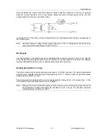
these conditions the output relay ON resistance together with the resistance of the fuse is typically
about 50
Ω
which results in a 2.5 V loss across output pins with a full load current of 50 mA. The
output schematic is shown in the figure below.
In the figure
OUT_A
and
OUT_B
refer to
Digital Output nA
and
Digital Output nB
pins, respectively, in
the I/O connector.
DC Output
The input voltage to the DCIN connector is circulated back to the I/O connector of the Arctic. See the
I/O connector’s pin description table shown in Chapter 6. This DC output can be used, for example,
together with digital outputs in order to simplify external circuitry and wiring.
Analog Input (IO-8-1-1 only)
The Arctic models with an optional analog input have a 12-bit A/D converter. The input is galvanically
isolated and is capable of measuring analog signals up to 60 V, making it ideal for general purpose
voltage measurement or control.
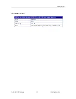
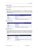
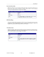
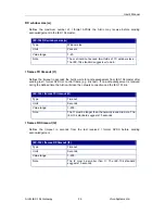
The analog input is unipolar and the pins are designated as
Analog Input+
and
Analog Input–
in the
I/O connector’s pin description table shown in Chapter 3.
Note:
Absolute maximum voltage across digital output pins is 30 V. Voltage levels above this value
may cause permanent damage to the PTC fuse.
Note:
Although the input is protected against reverse polarity and overvoltage the inputs should not
be subjected to voltages exceeding the specified 0 to 60 V range. The absolute maximum
voltage between input pins is ±100 V.


