background image

6

There are two EPL ports on the Pedestal control panel. One port is used to connect the Pedestal to the Control 
Panel via an EPL Node and the other port can be used to provide the EPL data communications to the Head. 
Although the Head and EPL Node can be connected to either of the ports, it is recommended that the Head is 
connected to the upper port, with the EPL Node connected to the lower port, to prevent the Head 
Communication cable from being dislodged by the Studio Floor cable as the pedestal moves around the studio.

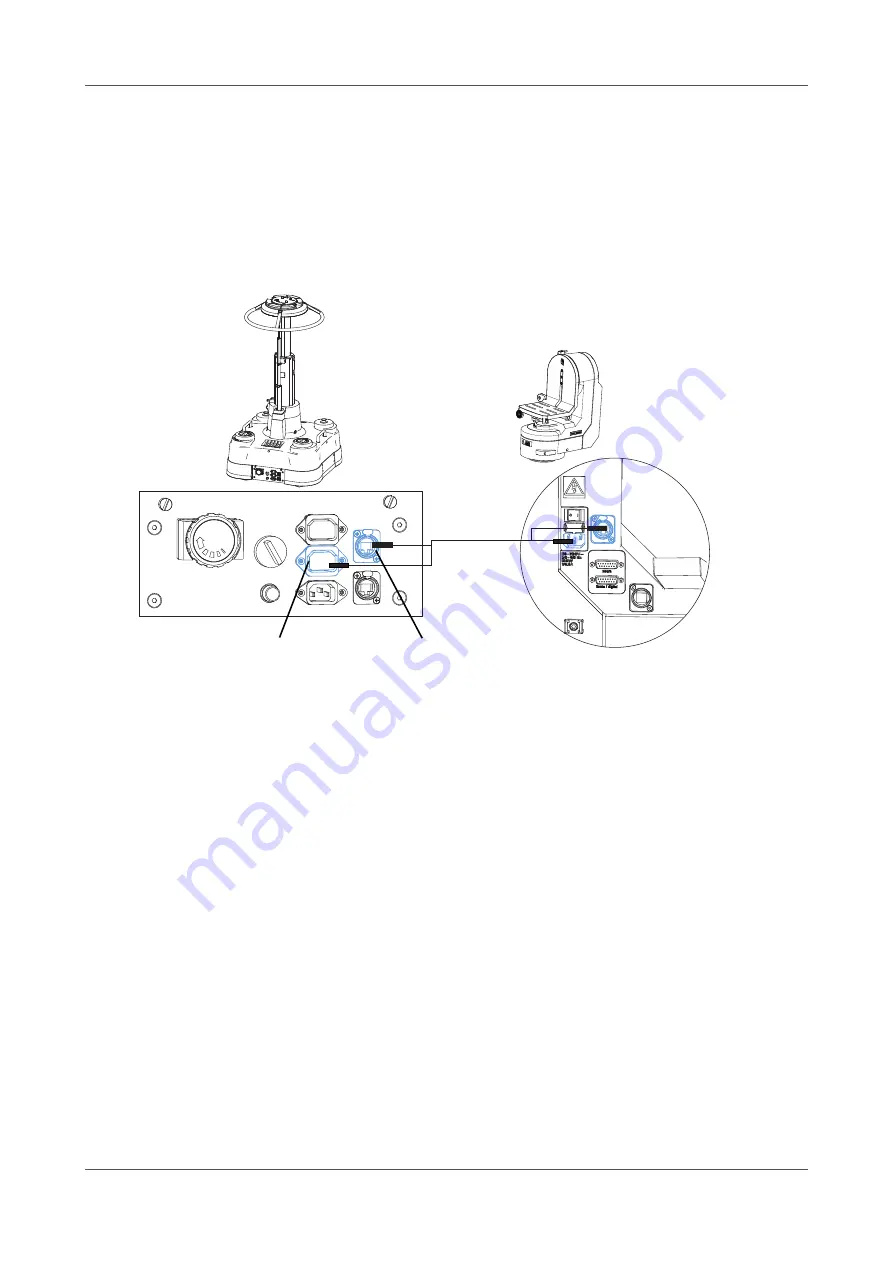
The power and EPL connections from the Fusion Pedestal (FP-145/FP-188) to the Head are shown in 

Figure 4

.

Connecting the Head to a Fusion Height Drive 

When the Head is mounted onto a manual only pedestal, a Fusion Height Drive (FBH-175) can be installed to 
remotely operate the height of the pedestal from a Vinten Radamec Control Panel. 

The Height Drive has two power output sockets and a single power inlet socket that is connected to the studio 
supply. The 

Head Power Output 

socket is used to supply power to the Head. Note that the 

Head Power 

Output

 socket is controlled by the Height Drive and therefore it is switched, fused and isolated on activation of 

the emergency stop button on the Height Drive. Each power connector on the Height Drive is fitted with a 
connector retaining clip to prevent the cable becoming dislodged causing accidental loss of power. Always 
ensure that the retaining clip is fastened. 

EPL connection to the Head is supplied by the 

EPL Out 

port on the Height Drive. The

 EPL In

 port connects to 

the Vinten Radamec Control Panel via the EPL Node. The Height Drive is supplied with a Head Communication 
cable that can be used to connect the Height Drive to the Head. 

The power and EPL connections from the Fusion Height Drive to the Head are shown in 

Figure 5

.

Figure 4   Fusion Pedestal to Head Power & EPL Connections

Head 

Communication 

cable

Head Power 

Output socket

Head EPL port

Содержание RADAMEC Fusion FH-100

Страница 1: ...Robotic and Manual Pan Tilt Head FH 100 Robotic Camera Control Systems Vinten RADAMEC BROADCAST ROBOTICS Operators Guide V3979 4980 Issue 3 0 ...

Страница 2: ...Fusion FH 100 Robotic and Manual Pan Tilt Head Operators Guide Publication Part No V3979 4980 Issue 3 0 ...

Страница 3: ...r record without the prior agreement and permission in writing of Vitec Group plc Trademarks Vinten Radamec and Vinten are registered trademarks of the Vitec Group plc Important information about this document Information contained in this document is subject to change Camera Dynamics Limited reserves the right without notice to make changes in equipment design or performance as progress in engine...

Страница 4: ...g the camera cradle 13 Operating the Head in Robotic mode 14 Centre of Gravity height adjustment 9 Setting the camera number 14 Switching to Robotic mode 14 Operating the Head remotely from the Vinten Radamec Control Panel 15 Operating the Head in Manual mode 16 Switching to Manual mode 16 Adjusting the pan and tilt drag 17 Maintenance 18 Routine checks 18 Regular cleaning 18 Changing the fuse 19 ...

Страница 5: ...ive to Head Power EPL Connections 7 Figure 6 Vinten Fusion Robot Control window 10 Figure 7 Set pan tilt height limits dialog box 11 Figure 8 Angles of travel on the pan and tilt axes 11 Figure 9 Engaging and releasing the tilt lock 13 Figure 10 Controlling pan movements using a joystick 15 Figure 11 Controlling tilt movements using the joystick 15 Figure 14 Fuse compartment 19 ...

Страница 6: ... vostro distributore per ricevere la traduzione delle istruzioni originali Paesi UE Latviešu Šajā operatora rokasgrāmatā iekļautie norādījumi sākotnēji tika sarakstīti angļu valodā un pēc tam pārtulkoti citās valodās Ja nesaprotat šos norādījumus svešvalodā sazinieties ar Vinten vai tirgotāju lai saņemtu norādījumu tulkojumu kādā no ES dalībvalstu valodām Lietuvių Šiame operatoriaus vadove pristat...

Страница 7: ...ectly you will help prevent potentially negative consequences for the environment and human health and help conserve natural resources For more information about disposing of this product visit www vintenradamec com support WEEE Certification This product conforms to the following European Directives 2006 42 EC CE Marking Directive 98 37 EC Machinery Directive 73 23 EEC Low Voltage Directive 2004 ...

Страница 8: ...entilate the product correctly Refer to the Technical Data section of this guide for the operating limits for the product Power sources Connect the product to a power supply of the type and voltage rating described in the Technical Data section of this Guide or as marked on the product For an emergency power down ensure all personnel are aware of the location of the power switch on the product and...

Страница 9: ...ent as the Head moves about the pan axis Personnel need to be trained and aware of how far the Head and Pedestal can move the speeds involved and the need to stay clear of robotic equipment at all times Warning Signs Warning signs should be displayed prominently in the workplace alerting personnel that robotic equipment is in use and may move suddenly without warning If personnel are working on ro...

Страница 10: ...c operation Yes Manual operation Yes Power consumption peak 250W Power input Autoranging 110 240V AC 50 60Hz System fuse T6 3A Physical Environment Performance Electrical WARNING This product has basic insulation only Class 1 The product requires an earth connection Pedestal tripod fixing four hole flat base Quickfix base heavy duty Quickfix adaptor Direct to Canon or Fujinon broadcast lenses A ra...

Страница 11: ...amp with 3 fixing screws 1 Camera cradle with camera mounting slots 2 Teleprompter mounting holes 3 Vanity mirror mounting holes optional 4 Pan drag adjustment dial 5 Teleprompter mounting clamp 6 Pan bar mounting 7 Tilt lock 8 1 2 3 4 7 5 8 6 7 ...

Страница 12: ...Analogue Lens 12 Focus Digital Port combined Analogue Lens focus port and Digital Lens RS232 port 13 Cable restraint 14 USB Port used for configuration and diagnostics 15 Power Input socket 16 Fuses 17 Power ON OFF switch 18 Power ON LED 19 EPL Port 20 Tilt drag adjustment dial 21 12 13 14 15 16 17 18 19 21 9 11 20 10 ...

Страница 13: ...x Four hole mounting plate with Quickfix base 22 Mounting plate fixing holes 4 off 23 WEEE label 24 Serial Number revision and part number information 25 24 25 23 22 ...

Страница 14: ...cluding four fixing bolts and washers used when mounting the Head onto a tripod or pedestal mounting plate a Vinten spanner and two telescopic pan bars for use when the Head is operated manually Optional accessories include a Vinten heavy duty Quickfix adaptor Part No 3490 3 that allows operators to easily and quickly mount and remove the Head from a pedestal or tripod and an Intermediate Plate Pa...

Страница 15: ...daptor The Quickfix adaptor has a safety latch mechanism that is used to secure the Head into position about the Quickfix base Figure 2 To mount the Head onto a Quickfix adaptor 1 Push up the red safety latch and unlock the adaptor by pulling the lever fully outwards and to the left 2 Position the Head in the adaptor ensuring that it seats correctly in the recess and the safety button is depressed...

Страница 16: ...ing bolts supplied with the camera mounting plate from the underside of the camera cradle through the mounting slots Mounting the payload When the camera is installed the remaining payload including viewfinder pan bars and teleprompter can be attached to the Head Fitting a teleprompter A teleprompter can be fitted to the Head using the mounting bracket supplied with the teleprompter The bracket is...

Страница 17: ... on the Head using a USB System Configuration cable Part No D200 103 Camera lens cabling The Head has an integral lens drive capability that can directly drive any full servo digital Canon or Fujinon broadcast lens A lens cable to suit a Canon or Fujinon lens can be supplied to connect to the camera lens to the Head A digital camera lens requires a single RS232 focus and zoom cable connected from ...

Страница 18: ...er and EPL data communications A shortened combined cable called the Head Communication cable is supplied with the Fusion Pedestal and Fusion Height Drive to provide direct connection between the Pedestal or Height Drive and the Head Connecting the Head to a Fusion pedestal When mounted onto a Fusion Pedestal FP 145 and FP 188 the power and EPL supply to the Head can be obtained directly from the ...

Страница 19: ...he Height Drive has two power output sockets and a single power inlet socket that is connected to the studio supply The Head Power Output socket is used to supply power to the Head Note that the Head Power Output socket is controlled by the Height Drive and therefore it is switched fused and isolated on activation of the emergency stop button on the Height Drive Each power connector on the Height ...

Страница 20: ...s before balancing the Head Any equipment fitted or adjusted later can unbalance the Head Figure 5 Fusion Height Drive to Head Power EPL Connections Warning The total camera payload can reach 55 kg 121 lb Take the necessary precautions to safely handle this weight before loosening the camera cradle fixing screws Switch OFF before attempting to balance the Head or making any adjustments to the came...

Страница 21: ...ent Fore and aft balance must be set before adjusting the payload centre of gravity C of G vertically to the tilt axis To set the centre of gravity height adjustment 1 Switch OFF power to the Head and engage the tilt lock 2 Loosen the three screws securing the camera cradle to the tilt drive and raise the camera cradle to vertically align the camera assembly centre of gravity with the tilt axis 3 ...

Страница 22: ...ower to the Head 7 On the laptop or PC double click the Fusion Setup Test icon on the desktop to launch the configuration software tool The Vinten Fusion Robot Control window appears as shown in Figure 6 8 In the Robot Type section select the Head option 9 In the Machine Version section select the options for the installed Head The options should default as shown in Figure 6 The Machine Version de...

Страница 23: ...nd tilt axes The Set pan tilt height limits dialog box appears as shown in Figure 7 Figure 6 Vinten Fusion Robot Control window a Robot Type section b Machine Version section c Zero Pan and Tilt button d Set Pan Tilt X Y and Height Limits button e Processor Reset button a b d c e ...

Страница 24: ...ne click Apply and then OK to close the dialog box 14 Click OK to close the Vinten Fusion Robot Control window Figure 6 15 Switch OFF the power to the Head 16 Disconnect the lead from the USB port and reconnect the EPL cable 17 Switch ON the power to the Head Figure 7 Set pan tilt height limits dialog box f Pan maximum and minimum limits g Tilt maximum and minimum limits Figure 8 Angles of travel ...

Страница 25: ...o its limits in both pan and tilt axes using the joystick to determine if the limits have been correctly set Warning Closely observe the camera movement while checking the software axis limits to avoid potential personal injury or damage to the equipment ...

Страница 26: ...k prevents the camera cradle from moving on the tilt axis The tilt lock mechanism is operated by a button located on the top of the Head as shown in Figure 9 To engage the tilt lock 1 Steady and hold the camera cradle in the horizontal position 2 Lift the tilt lock button upward whilst gentle rocking the camera cradle side to side until the button latches To release the tilt lock 1 Gently rock the...

Страница 27: ...e camera online it must be enabled from the Control Panel before the camera can be controlled 1 Select the camera on the control panel 2 Select OPTS ENABLE to bring the camera online 3 Check that the pan and tilt robotic manual rotary switches on the Head rotate to auto setting There is an audible click when the switch rotates between settings 4 The camera button on the Control Panel changes to wh...

Страница 28: ...igure 11 Controlling tilt movements using the joystick Zero Pan Pan right Pan left Move joystick to the left to pan left Move joystick to the right to pan right Move joystick backward to tilt the camera upward Move joystick forward to tilt the camera downward ...

Страница 29: ...ges the robotic drives and engages drag modules allowing the camera operator to smoothly control the camera using the pan bars Pan and tilt axes can be independently set to manual mode by turning the appropriate pan or tilt robotic manual rotary switch fully clockwise and then rotating the axis until the drag module engages Warning The FH 100 Head can be used remotely from a Control Panel Ensure t...

Страница 30: ...he camera cradle and the tilt drag adjustment dial is positioned above the connections on the side of the Head see Features and Controls on page viii To increase drag turn the dial clockwise and to decrease drag turn the dial counter clockwise as shown in Figure 13 Note The whip pan facility is not affected by the pan drag setting Figure 13 Adjusting the pan tilt drag Turn the dial in the directio...

Страница 31: ...nly be cleaned with a semi stiff brush or a vacuum cleaner During normal use the only cleaning required should be a regular wipe over with a lint free cloth Dirt accumulated during storage or periods of disuse may be removed with a semi stiff brush Particular attention should be paid to the four hole mounting and camera mounting faces along with all the connection ports Warning To reduce the risk ...

Страница 32: ...e compartment Figure 14 4 Replace the failed fuse and then replace the fuse compartment pushing firmly into place 5 Switch ON power to the Head Adjusting the drag control dials The pan and tilt drag control dials may require adjustment after prolonged use These adjustments must be carried out by competent persons Contact Vinten Radamec for servicing the FH 100 pan tilt Head Figure 14 Fuse compartm...

Страница 33: ...line and grey when the camera is offline and the Head set to manual operation Switching to Robotic mode Check the Head fuses and replace as necessary The Head requires two T6 3A fuses Changing the fuse Camera and payload moving to far on the pan and tilt axis in robotic operation Check the pan and tilt limits using the Fusion Setup Test configuration software tool Setting pan and tilt movement lim...

Страница 34: ...rol Interface digital servo lens V4050 0002 Vinten Radamec Fujinon analogue Hand Control Interface analogue servo lens V4050 0003 Vinten Radamec Fujinon digital Hand Control Interface digital servo lens V4050 0004 Vinten Radamec Canon analogue Hand Control Interface digital servo lens V4050 0005 Spares Fuse 6 3 AT ceramic time delay 21 0168 0020 Configuration Tools USB system configuration cable D...

Страница 35: ...22 ...

Страница 36: ...on pedestal 5 connection ports 17 Control Panel 5 Control Panel selecting robotic mode 14 D drag adjustment dials 16 drag control dials adjusting 18 E electrical connection 17 emergency stop button pedestal 5 EPL cables 5 EPL Node 5 EPL Output port Height Drive 5 Ethernet ports 5 external ports 5 F fixing bolts standard accessory 2 focus digital port 7 fuse compartment 18 fuse changing 18 fuses ch...

Страница 37: ... adaptor Vinten heavy duty 2 Quickfix base 2 R Regular cleaning 17 Robotic mode 14 robotic manual rotary switches 14 Routine checks 17 S Spares 20 T teleprompter 3 8 teleprompter balance 8 tilt axis 12 tilt drag adjustment dial 16 tilt lock 3 8 tripod Vinten heavy duty 2 Troubleshooting 19 U unbalanced payload 8 unpacking the Head 1 USB port 7 12 USB System Configuration 10 V viewfinder 3 8 Vincon...

Страница 38: ...ch Germany Tel 49 671 483 43 30 Fax 49 671 483 43 50 Camera Dynamics GmbH Erfurter Straße 16 85386 Eching Germany Tel 49 89 321 58 200 Fax 49 89 321 58 227 JAPAN Vinten Japan KK P A Bldg 5F 3 12 6 Aobadai Meguro ku Tokyo 153 0042 Japan Tel 81 3 5456 4155 Fax 81 3 5456 4156 SINGAPORE Camera Dynamics Pte Ltd 6 New Industrial Road 02 02 Hoe Huat Industrial Building Singapore 536199 Tel 65 6297 5776 F...

Отзывы: