NT-50906901-KSDR-ECOWATT-48-88-120-AN-170907
28/68
ENGLISH
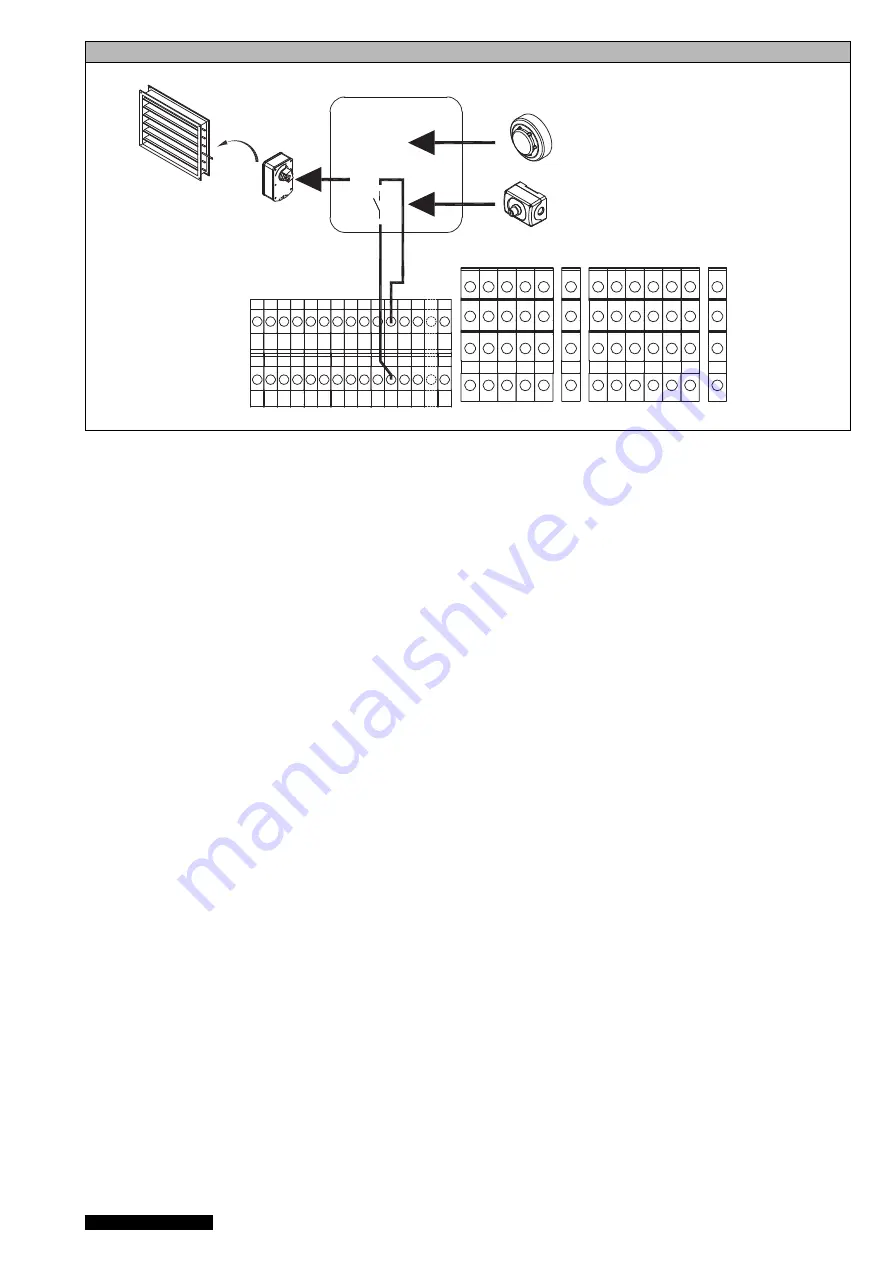
Operation with a DAD system - supply fi re damper
23
7
5
3
1
25 27
21
41
35
33
31
61 63
37
24
8
6
4
2
26 28
22
42
36
34
32
62 64
38
+24V+24V+24V
G0
G0
B3
+24V
24V
A04
A03
A02
A01
10
9
12
11
14
13
24V 24V 24V
ON
24V
A04
24V
D
V+
B2
B1
16
15
24V
A05
BREA
DAD S4 T1
OX-08
C
R
G0 G0 G0 G0 G0 G0
Unit control
terminal block
Fire damper with
spring back actuator
Dampers, DAD and sensors are accessories.
7. COMMISSIONING
All KSDR ECOWATT
®
units are subject to an EC control and a function test before they are delivered.
Factory inspection of units:
• Electrical conformity tests: Earth bonding / Insulation of powered-up parts.
• Control of temperature sensor readings (Supply temp., exterior temp., anti-freeze temp. according
to option).
• Control of supply fan alone (Control of corresponding fl ow sensor).
Factory confi guration of units:
• Ventilation mode = CAV mode (description § "8.2 Constant fl ow operation (CAV)", page 33).
• High speed = Max. fl ow of the unit, Low speed = Max. fl ow / 2.
• Plug fan type: determined according to the fl ow coeffi cient K, particular to fans (description
§ "8.12 Measuring air fl ows - modifying the coeffi cient K", page 44)
• Heating mode = constant supply temp. (description in § "8.5 Temperature adjustment", page 36).
• Coil/electric heater type (description in
"Operating modes"
paragraph
: Implementation of the
unit"
): according to the requested option if the unit does not have a Coil/electric heater, the electrical
resistance is selected by default).
The controller must be commissioned and confi gured by a qualifi ed person in respect of the safety instruc-
tions described in § "1.2 Safety guidelines", page 4. In Mainland France, this service can be provided
by VIM and its qualifi ed service providers.
Contact us
. It can only occur once the installation and electrical,
air fl ow and hydraulic wiring operations are complete.
Before commissioning and confi guration, ascertain the necessary data, fl ows, pressures, temperatures,
desired operating mode and installation diagrams:
• Make sure that the device does not contain any foreign bodies.
• Check that all the components are fastened in their original locations.
• Manually check that the fan does not scrape and is unblocked.
• Check that all exterior electrical parts are connected.
• Check that electrical connections/ground connection are sealed.
• Check voltages, intensities, gauges of thermal protections.
• Check the rotating direction of the fan - the direction of the air fl ow.
• Check the air fl ow rate.
• Check for any clogging of the fi lter - clean or change it as necessary.
• Enter the adjustment parameters, simulate the operation of coils/alarms/safety procedures.


