VIKING TECHNICAL SUPPORT 1.800.908.0884
1 7
Limit Switch Setup
GATE OPERATOR INSTALLATION
STEP 1
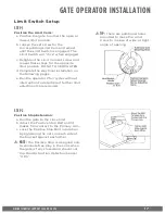
Position the Limit Cams:
a. Position the gate to either the open or
closed limit position.
b. Loosen the set screw for the
corresponding Limit Cam and adjust
until the Limit Switch is engaged. The
Limit Switch will “click” when engaged.
c. Retighten the Limit Cam set screw and
repeat these steps for the opposite
limit position. DO NOT OVERTIGHTEN.
d. Complete the electrical installation on
the following pages.
e. Run the operator 2 full cycles without
interruption to determine if further limit
adjustments are required.
STEP 2
Positive Stop Extension:
a. Run the gate to the close limit.
b. Adjust the Positive Stop Bolt until it
makes firm contact to the Primary Arm.
c. Lock the Positive Stop Bolt in position
by tightening the nuts on each side of
the bracket against each other.
!
NOTE:
The Positive Stop is designed only
to eliminate free play in the arms when
the gate is fully closed and should not
trip the Obstruction Detection Sensor
“ODS”.
!
TIP:
There are additional holes
provided to move the Limit
Cams to in case of wide or tight
angle of opening


