background image

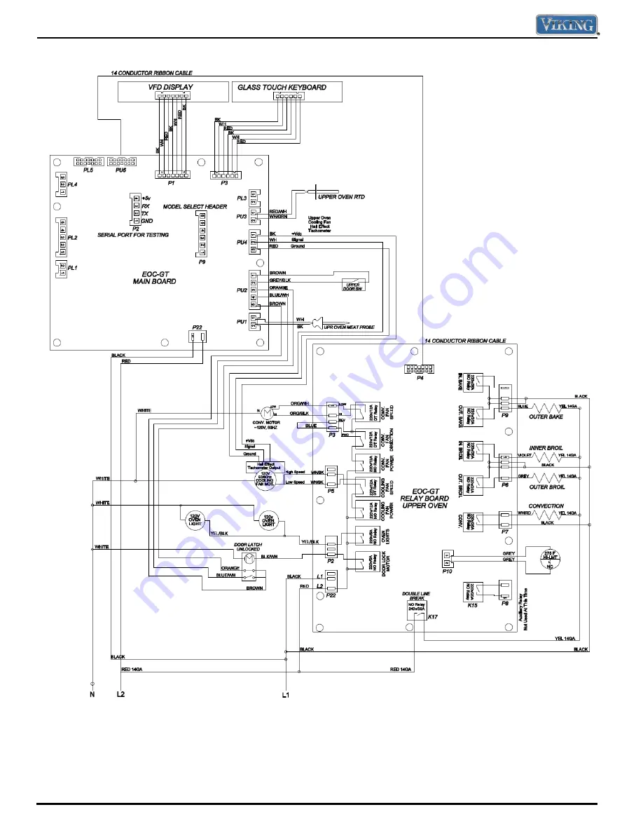
Wiring and Schematics 


© 2010 Viking Preferred Service 


66


Wiring Diagram – DSOE305T 

Содержание Designer DDOE305T

Страница 1: ...iking does not assume any responsibility for property damage or personal injury for improper service procedures done by an XQTXDOL HG SHUVRQ Service Manual This Base Manual covers general and VSHFL F LQIRUPDWLRQ LQFOXGLQJ EXW QRW limited to the following models DSOE305T DDOE305T Single and Double Wall Oven ...

Страница 2: ...ne Break Relay 37 Bake Element 37 Bake Relay 38 Broil Element 38 Broil Relay Inner and Outer 39 Inner Broil Relay 39 Outer Broil Relay 39 Convection Element 39 Convection Relay 40 Cooling Fan 40 Fan Relay 41 Fan Hi Speed 41 Convection Fan 42 Convection Operation 42 Clockwise FWD Low Speed 42 Clockwise FWD High Speed 42 Description Page Testing Relay Board 42 Door Lock Assembly 43 Testing Lock Moto...

Страница 3: ...BEGINNING REPAIRS Pride and workmanship go into every product to provide our customers with quality appliances It is possible however that during the lifetime of a product service may be required Products should be serviced only by a qualified authorized service technician who is familiar with the safety procedures required to perform the repair and is equipped with the proper tools parts testing i...

Страница 4: ...es are but not limited to bed and breakfasts fire stations private clubs churches etc This warranty excludes all commercial locations such as restaurants food service locations and institutional food service locations This warranty extends to the original purchaser of the product warranted hereunder and to each transferee owner of the product during the term of the warranty This warranty shall appl...

Страница 5: ...on IMPORTANT Retain proof of original purchase to establish warranty period The return of the Owner Registration Card is not a condition of warranty coverage You should however return the Owner Registration Card so that Viking Range Corporation can contact you should any question of safety arise which could affect you Any implied warranties of merchantability and fitness applicable to the described...

Страница 6: ... 50 amp service with its own circuit breaker Maximum amp usage 23 3 amps 240 VAC 20 2 amps 208 VAC 46 7 amps 240 VAC 40 5 amps 208 VAC Oven interior width 24 3 4 62 9 cm Oven interior height 15 3 4 40 0 cm Oven interior depth 18 45 7 cm Upper 18 45 7 cm Lower 19 48 3 cm Oven volume measured to AHAM Standard 4 1 cu ft Upper 4 1 cu ft Lower 4 1 cu ft Oven volume total oven cavity 4 3 cu ft Upper 4 3...

Страница 7: ...ed Service 7 7 General Information 51 1 2 130 8 cm 51 1 2 130 8 cm 25 3 16 59 7 cm 25 3 16 59 7 cm 29 3 4 75 6 cm 29 3 4 75 6 cm 29 1 2 74 9 cm 25 3 16 59 7 cm 46 3 16 113 0 cm 21 1 4 53 9 cm General Information Dimensions ...

Страница 8: ...Õ ÌÊ ÕÃÌÊLiÊ i ÌÊÌ ÊÌ i top left for a flush installation NEVER cut the conduit UÊÊ Ê iVÌÊÌ iÊyiÝ L iÊ À Ài ÊV L iÊ ÀiVÌ ÞÊ to 4 wire 240V household service If codes permit and separate grounding wiring is used we recommend that a qualified electrician determine the grounding path and that the wire gauge is in accordance with local codes UÊÊ Ê Ê Õ VÌ ÊL ÝiÃÊ ÃÌ i Ê ÊÀi ÀÊÜ directly behind oven must ...

Страница 9: ...ent or surrounding areas until they have had sufficient time to cool UÊÊ Ê Ê Ì iÀÊ Ìi Ì ÞÊ ÌÊÃÕÀv ViÃÊ V Õ iÊ Ûi Ê vent surfaces near the vent opening oven door areas around the oven door and oven window UÊÊ Ê Ê iÊ ÃÕÃiÊ vÊ Ûi Ê ÀÃÊ i ÊÃÌi Ê sitting or leaning on them can result in potential hazards and or injuries CAUTION NEVER use appliance as a space heater to heat or warm a room to prevent pote...

Страница 10: ...ng cycles you may sense an odor characteristic of high temperatures KEEP THE KITCHEN WELL VENTED DURING THE SELF CLEAN CYCLE General Information CAUTION The oven is heavy use extreme care when handling WARNING This features a self cleaning cycle During this cycle the oven reaches elevated temperatures in order to burn off soil and deposits A powder ash residue is left in the bottom of the oven aft...

Страница 11: ...6 et les electrique domestiques CAN USA C22 2 No 1 M 89 C US PEO20061 Serial Number Month Day Year of Manufacture 03 22 10 C00011288 General Information Model Serial Number Matrix The serial number and model number for your appliance are located on the identification plate mounted on the underside of the control panel Model Numbers Serial Numbers D D O E 3 0 5 T S S D Viking Designer Series Electri...

Страница 12: ...ivated when the oven is not in use Settings Accesses custom features such as display brightness Sabbath mode and tones Settings and Functions Control Panel Bake Conventional single rack baking breads cakes cookies pastry pies entrees vegetables Convection Bake Multi rack baking for heavier or frozen foods e g frozen pies pizzas entrees vegetables Defrost Natural defrosting of food using fan withou...

Страница 13: ... Use this setting to gently brown meringue on racks 3 or 4 in 3 4 minutes TRU CONV TruConvec The rear element only operates at full power There is no direct heat from the bottom element The motorized fan in the rear of the oven circulates air in the oven cavity for even heating Use this setting for foods that require gentle cooking such as pastries souffles yeast breads quick breads and cakes Bread...

Страница 14: ...Clean This oven features an automatic pyrolytic self cleaning cycle During this cycle the oven reaches elevated temperatures in order to burn off soil and deposits An integral smoke eliminator helps reduce odors associated with the soil burn off A powder ash residue is left in the bottom of the oven after completion of the self clean cycle The door latch is automatically activated after selecting ...

Страница 15: ...ork out of roasting by cooking foods to the ideal internal temperature The probe temperature setting is used to automatically turn the oven off when the internal temperature of the meat being roasted is reached PROOFING This function uses a low temperature to create an optimal environment for the yeast to rise in many types of dough This setting is designed for allowing yeast dough to rise to a te...

Страница 16: ...e to remove encrusted material soak area with hot wet towels to loosen the material then use a wooden or nylon spatula or scraper DO NOT use a metal knife spatula or any other metal tool to scrape stainless steel surfaces Scratches are almost impossible to remove Brass Parts Broiler Pan and Grid Clean with detergent and hot water For stubborn spots use a soap filled steel wool pad Oven Racks Clean ...

Страница 17: ...eat probe is open or shorted or it may be a defective probe jack Check the meat probe and jack repair or replace as necessary Latch Error Time of Day and Latch Error The control is unable to lock or unlock the door latch Verify power to the lock motor and check door interlock switches Keyboard Error Time of Day and Keyboard Error No connection exists between the keyboard and the control Verify the...

Страница 18: ... Depress the SETTINGS button on the control panel You will see the word SETTINGS in the upper left corner of the screen and the BRIGHTNESS parameter 3 Using the DOWN ARROW pad scroll down until you see TIMEOUTS in the display 4 Touch and hold the down arrow pad for five seconds you will hear three tones until the display changes from TIMEOUTS to TESTS VQQFS PWFO TFMFDU NPEF DMPDL TFUUJOHT CSJHIUOFT...

Страница 19: ...ALL TESTS You are now in the diagnostic mode When you have entered the diagnostic mode you will be able to run the following nine main test programs 1 Run all tests 2 Product Information 3 Individual display tests 4 Individual upper oven tests DDOE305T Individual oven tests DSOE305T 5 Individual lower oven tests DDOE305T 6 Individual keyboard tests 7 Run all upper oven tests DDOE305T Run all oven ...

Страница 20: ...Up or Down arrow 3 Clear Screen All digits in the display will extinguish Enter Up or Down arrow 4 Upper Inner Bake Element SKIP THIS TEST No amperage should be read on Step 4 Not used on DSOE and DDOE models Enter Up or Down arrow 5 Upper Outer Bake Element Run bake element Enter Up or Down arrow 6 Upper Inner Broil Element Run inner broil element Enter Up or Down arrow 7 Upper Outer Broil Elemen...

Страница 21: ...r broil element Enter Up or Down arrow 25 Lower Convection Element Run convection element Enter Up or Down arrow 26 Lower Oven Temperature Display lower oven temperature Enter Up or Down arrow 27 Lower Meat Probe SKIP THIS TEST No lower meat probe on the DDOE305T Default 0 degrees Enter Up or Down arrow 28 Lower Cooling Fan High speed Run cooling fan at high speed Enter Up or Down arrow 29 Lower C...

Страница 22: ...ill advance to next test 52 Press PROOF pad Pressing Proof pad will advance to next test 53 Press CLEAR pad Pressing Clear pad will advance to next test 54 Press TIMER pad Pressing Timer pad will advance to next test 55 Press COOK TIME pad Pressing Cook Time pad will advance to next test 56 Press CLOCK pad Pressing Clock pad will advance to next test 57 Press STOP TIME pad Pressing Stop Time pad w...

Страница 23: ...Settings pad will advance to next test 79 Press ENTER pad Pressing Enter pad will advance to next test 80 Press 0 pad Pressing 0 pad will advance to next test 81 Press CLEAR pad Pressing Clear pad will advance to next test Single oven model Double oven model 2 Product Information This test will allow you to see the model version and serial number of the microprocessor To enter this test enter diag...

Страница 24: ... the component test Step To test Test Result To exit 1 Press SET pad Display all dots and segments All digits in the display will light up Enter Clear or Down arrow 2 Press SET pad Clear screen All digits in the display will extinguish Enter Clear or Down arrow To exit this test select ENTER CLEAR or down arrow pad 4 Individual upper oven tests DDOE305T Individual oven tests DSOE305T This test wil...

Страница 25: ...s meat probe temp with probe inserted in socket default is 0 F with no probe inserted Enter Clear or Down arrow 8 Press SET Cooling Fan High speed Run cooling fan high speed Enter Clear or Down arrow 9 Press SET Cooling Fan Low speed Run cooling fan low speed Enter Clear or Down arrow 10 Press SET Convection Fan High speed Run convection fan high speed Enter Clear or Down arrow 11 Press SET Convec...

Страница 26: ...RROW pad to scroll to the Individual lower oven test and press the ENTER Pad When you have selected this test the first screen you will see will be the one shown below The following is a table consisting of all the individual components that can be tested in this program To scroll through each test use the UP ARROW or DOWN ARROW pad and then press SET or ENTER to run the selected component test Ste...

Страница 27: ...speed Same as upper convection fan Enter Clear or Down arrow 11 Press SET Convection Fan Low speed Same as upper convection fan Enter Clear or Down arrow 12 Press SET Convection Fan Low speed reverse Same as upper convection fan Enter Clear or Down arrow 13 Press SET Convection Fan High speed reverse Same as upper convection fan Enter Clear or Down arrow 14 Press SET Door Switch Check door interlo...

Страница 28: ...see will be the one shown below To access an individual key follow the steps below 1 Touch the SET or ENTER pad 2 You will see the BAKE KEY in the display 3 Using the UP ARROW or DOWN ARROW pad scroll to the individual pad that you wish to test For example if you wish to test the Defrost pad cycle through all the pads until the Defrost pad is displayed 4 Touch the SET or ENTER pad 5 The display wi...

Страница 29: ...TER to run the selected component test Step Test Result To Change Test 1 Upper Inner Bake Element SKIP THIS TEST No amperage should be read on Step 1 Not used on DSOE and DDOE models Enter Up or Down arrow 2 Upper Outer Bake Element Run bake element Enter Up or Down arrow 3 Upper Inner Broil Element Run inner broil element Enter Up or Down arrow 4 Upper Outer Broil Element Run outer broil element ...

Страница 30: ...mponents are tested This test will cycle the entire lower oven double oven models elements fans lights door interlock switches and door lock motors in succession To enter this test enter diagnostic mode see accessing the diagnostic section page 18 With the unit in diagnostic mode press the DOWN ARROW pad to scroll to the RUN ALL LOWER OVEN TESTS and press the ENTER Pad When you have selected this ...

Страница 31: ...3 Lower Convection Fan High speed reverse Run convection fan at high speed reverse Oven uses a single direction convection motor Same direction as low speed Enter Up or Down arrow 14 Lower Door Switch Check door interlock Enter Up or Down arrow 15 Lower Oven Lights Check lower cavity lights Enter Up or Down arrow 16 Lower Door Lock Door lock motor is advanced Enter Up or Down arrow 17 Lower Door U...

Страница 32: ...18 Press COOK TIME pad Pressing the Cook Time pad will advance to the next test 19 Press CLOCK pad Pressing the Clock pad will advance to the next test 20 Press STOP TIME pad Pressing the Stop Time pad will advance to the next test 21 Press RECIPES pad Pressing the Recipes pad will advance to the next test 22 Press UPPER OVEN pad Pressing the Upper Oven pad will advance to the next test 23 Press O...

Страница 33: ...e 7 pad will advance to the next test 39 Press 8 pad Pressing the 8 pad will advance to the next test 40 Press 9 pad Pressing the 9 pad will advance to the next test 41 Press SETTINGS pad Pressing the Settings pad will advance to the next test 42 Press ENTER pad Pressing the Enter pad will advance to the next test 43 Press 0 pad Pressing the 0 pad will advance to the next test 44 Press CLEAR pad P...

Страница 34: ...edures Parts Location Relay Board P7 Convection Element K17 Line Break P10 High Limit P6 Outer Broil P6 Inner Broil P9 Bake P2 Oven Door Light P2 Oven Door Lock Motor P5 Cooling Fan Motor P3 Convection Fan Motor P 4 Power Supply P22 Line Input K1 K2 K3 K4 K5 K6 K7 ...

Страница 35: ...ch Key Board PL3 Lower RTD PU3 Upper RTD P1 VFD Display P9 Model Select PL2 Door Latch Switch Lower PL1 Meat Probe Lower PL4 Hall Effect Sensor Lower P2 Serial Port PU1 Meat Probe Upper PU2 Door Latch Switch Upper PU4 Hall Effect Sensor Upper Insure that the upper and lower RTDs are installed to correct connections ...

Страница 36: ...089 ї room temp Door Latch Motor P22 Black White N terminal block 2 4 K 1 Lower Door Switch PL2 Gray PL2 Violet White Infinite 1 door open 0 1 door closed Upper Door Switch PU2 Gray PU2 Violet White Infinite ї door open 0 ї door closed Upper Door Lock Switch S1 PU2 Blue PU2 Brown 0 ї Door unlatched Infinite ї door latched Upper Door Lock Switch S2 PU2 Orange PU2 Brown Infinite ї door unlocked 0 ї door...

Страница 37: ...t a cooking program When the relay contact is closed D25 LED at base of relay is illuminated red 240 VAC should be measured between the yellow wire and L1 black If 0 VAC is measured disconnect power and remove the red and yellow wire off the relay With power applied use an Ohmmeter to check for continuity between the two relay contacts with the relay energized If infinite resistance is measured thi...

Страница 38: ...ng Broil Element Locate the P6 connector and the line break relay on the relay board The P6 connector will have a Molex plug containing a violet black and gray wire The violet wire goes to the inner broil element the black wire is L1 input from main power supply and the gray wire goes to the outer broil element With the power off and Molex connector removed from the P6 relay board connection use a...

Страница 39: ...lay Select a cooking program When the outer relay contact is energized D21 LED at base of relay illuminates red check for 240 VAC between the yellow wire at the line break relay and the gray wire on P6 If 0 VAC is measured disconnect power and remove P6 Molex plug Reconnect power and using an Ohmmeter check for continuity between the two relay contacts When the relay is energized if infinite ohms ї...

Страница 40: ...ntacts When the relay is energized if infinite ohms ї are measured this indicates a bad relay and you will need to replace the relay board If 0 ohms are measured the relay contact is closing Cooling Fan Locate the P5 connector on the relay board The P5 connector will have a Molex plug containing white black wires With the Molex connector removed from the P5 board connection use an Ohmmeter to measu...

Страница 41: ...ven temperature reaches 400 F 204 5 C the EOC switches to HIGH speed When the oven is turned off cycle selector in OFF position the fan switches from high to low when the temperature at the RTD drops below 375 F 190 5 C and shuts off completely when the temperature drops below 250 F 121 C To test disconnect power and disconnect P11 Molex plug With voltmeter set for AC voltage check between neutral...

Страница 42: ... of the convection fan system The photo below shows the relay energized Low Speed Clockwise FWD When closed it sends power through the relay and out to the LO speed relay contact The output from the relay is connected to the C common terminal Because the relay is not used both the FWD and REV contacts are jumped together Clockwise FWD High Speed The speed relay is a SPDT relay When not energized t...

Страница 43: ...s the door liner and pulls inwards the S2 switch plunger is actuated The switch contact is closed and a completed circuit is made at PL2 lower oven and PU2 upper oven connection between the light brown and orange wires This signals the board that the door is locked When it is in time to unlock the door power is sent to the door lock motor and it continues its rotation The plunger releases the door...

Страница 44: ...t brown The reading should be zero 0 ї The S2 switch is N O and will read infinite ohms when the door is unlocked Shown below is the closed circuit in red When the door locks the S1 switch N O is no longer in contact with the motor cam and will read infinite ohms The S2 switch is N O and should close when the door is locked To test ohm out the orange and light brown wires The reading should read zer...

Страница 45: ...00 1350 300 1553 350 1654 400 1754 450 1852 500 1950 550 2047 600 2153 650 2238 700 2332 750 2425 800 2318 850 2609 900 2700 Note Door switch must be depressed in order for the convection fan and all convection cycles Auto Roast and Dehydrate heating elements to operate when the door is opened Test Main Power Board The main power board receives power directly from the power supply Verify 240 VAC b...

Страница 46: ...t and there is 240 Voltages being supplied to the Relay board replacement of the relay board is necessary If the voltages are correct reconnect the 3 wire Molex plug Place meter leads in pin 1 red and pin 2 white Activate the oven so that the fan is energized With the fan turning 2 5 VDC should be measured If 2 5 VDC is present then connect meter leads between pin 2 white and pin 3 black A voltage...

Страница 47: ... 2010 Viking Preferred Service 47 Service Diagnostics and Procedures Parts Location Oven Top Relay Board lower oven Terminal Block Main Control Board Relay Board upper oven Note DDOE305T model shown ...

Страница 48: ...rrect earth ground and polarization After servicing reconnect electrical power Main Top Front Disassembly To access main top front 1 Slide the unit out 6 8 2 Remove screws securing front top panel 3 Remove panel 4 Reverse to reassemble Main Top Rear Disassembly To access main top rear 1 Slide unit out of installation 2 Remove main top front see Main Top Front Disassembly on left 3 Remove screws se...

Страница 49: ...nd Main Top Rear Disassembly page 48 2 Main control board is accessible 3 Label and disconnect wiring 4 Remove screws securing main control board 5 Repair or replace main control board as necessary 6 Reverse procedure to reinstall Note DDOE305T model shown Service Diagnostics and Procedures Disassembly WARNING To avoid risk of electrical shock personal injury or death disconnect electrical power t...

Страница 50: ...main top front and main top rear see Main Top Front and Main Top Rear Disassembly page 48 2 Disconnect wiring from main control board to display and keyboard 3 Remove screws securing control panel Service Diagnostics and Procedures Disassembly WARNING To avoid risk of electrical shock personal injury or death disconnect electrical power to unit before servicing Wires removed during disassembly mus...

Страница 51: ...procedure to reinstall Note When replacing touch board make sure that center connection seats before installing screws Note DDOE305T model shown WARNING To avoid risk of electrical shock personal injury or death disconnect electrical power to unit before servicing Wires removed during disassembly must be replaced on proper terminals to insure correct earth ground and polarization After servicing r...

Страница 52: ...Preferred Service 52 Service Diagnostics and Procedures Parts Location Oven Convection Fan Broil Element Convection Fan Cover Oven Light Oven Light Bake Element Smoke Eliminator RTD Sensor Note DDOE305T model shown ...

Страница 53: ...rvice 53 Service Diagnostics and Procedures Parts Location Back Lower Cooling Fan Motor Convection Fan Convection Fan Lower Bake Element Upper Bake Element RTD Sensor RTD Sensor Upper Cooling Fan Motor Note DDOE305T model shown ...

Страница 54: ... from receiver 3 Close oven door to the broil stop position 4 Lift door up and out 5 Reverse procedure to reinstall Note DSOE305T model shown WARNING To avoid risk of electrical shock personal injury or death disconnect electrical power to unit before servicing Wires removed during disassembly must be replaced on proper terminals to insure correct earth ground and polarization After servicing reco...

Страница 55: ...m installation 2 Slide the unit out until rear cover is accessible 3 Remove upper rear cover see Upper Rear Cover Disassembly on left 4 Remove screws securing lower rear cover 5 Remove panel 6 Reverse to reassemble Note DDOE305T model shown WARNING To avoid risk of electrical shock personal injury or death disconnect electrical power to unit before servicing Wires removed during disassembly must b...

Страница 56: ...ge 55 5 Remove cooling fan see Oven Cooling Fan Disassembly page 62 6 Slide door lock assembly through cooling fan opening at rear of unit 7 Disconnect wiring Note A string or wire should be tied to the old latch hook so that when the new latch is replaced the service technician can use the wire to pull the hook and latch through the front frame 8 Repair or replace door lock assembly as necessary ...

Страница 57: ...cavity 3 Slide sensor into oven cavity and disconnect wiring 4 Repair or replace RTD sensor as necessary 5 Reverse procedure to reinstall Service Diagnostics and Procedures Disassembly WARNING To avoid risk of electrical shock personal injury or death disconnect electrical power to unit before servicing Wires removed during disassembly must be replaced on proper terminals to insure correct earth g...

Страница 58: ...convection element into cavity and disconnect wiring 5 Repair or replace convection element as necessary 6 Reverse procedure to reinstall WARNING To avoid risk of electrical shock personal injury or death disconnect electrical power to unit before servicing Wires removed during disassembly must be replaced on proper terminals to insure correct earth ground and polarization After servicing reconnec...

Страница 59: ...ews securing convection fan assembly to oven cavity 7 Disconnect wiring 8 Remove convection fan assembly 9 Repair or replace convection fan assembly as necessary 10 Reverse procedure to reinstall Note Removing the convection fan is a two man operation Service Diagnostics and Procedures Disassembly WARNING To avoid risk of electrical shock personal injury or death disconnect electrical power to uni...

Страница 60: ... rack support 1 Remove oven door see Door Removal page 54 2 Remove screws and rack supports from each side of oven cavity 3 Reverse procedure to reinstall Service Diagnostics and Procedures Disassembly WARNING To avoid risk of electrical shock personal injury or death disconnect electrical power to unit before servicing Wires removed during disassembly must be replaced on proper terminals to insur...

Страница 61: ...see Upper Rear Rear Cover Disassembly page 55 3 Remove oven cooling fan see Oven Cooling Fan page 62 4 Disconnect wiring remove screws securing rear trim pieces and remove trim 5 Carefully remove insulation covering bake element WARNING To avoid risk of electrical shock personal injury or death disconnect electrical power to unit before servicing Wires removed during disassembly must be replaced o...

Страница 62: ...d To access the cooling fan 1 Slide unit out of installation 2 Remove rear cover see Upper Rear Rear Cover Disassembly page 55 3 Remove screws securing cooling fan 4 Remove fan and disconnect wiring to fan and Hall Effect Sensor 5 Repair or replace cooling fan as necessary 6 Reverse procedure to reinstall WARNING To avoid risk of electrical shock personal injury or death disconnect electrical powe...

Страница 63: ...move side cover screws slide out side cover and remove insulation 7 Meat probe socket is now accessible 8 From inside the oven cavity remove nut and toothed washer to repair or replace meat probe socket 9 Reverse procedure to reinstall WARNING To avoid risk of electrical shock personal injury or death disconnect electrical power to unit before servicing Wires removed during disassembly must be rep...

Страница 64: ... board P1 white to black Defective oven wiring shorted open or burned Open Relay board Repair replace defective wiring Replace relay board check operation of blower motor Bake element inoperable Defective oven wiring Bake element Relay board Repair replace wiring Test bake element Verify relay operation wiring and inputs Broil element inoperable Defective oven wiring Broil element Relay board Repa...

Страница 65: ...motor Ohm oven sensor Replace relay board Repair or replace defective relay Repair or replace defective wiring Oven lights inoperable bulbs OK Relay board Open relay Defective oven wiring shorted open or burned Replace relay board Replace relay board Repair or replace defective wiring Oven light will not work Light bulb is burned out Supply voltage Check bulb and replace if defective Verify source...

Страница 66: ...Wiring and Schematics 2010 Viking Preferred Service 66 Wiring Diagram DSOE305T ...

Страница 67: ...Wiring and Schematics 2010 Viking Preferred Service 67 Wiring Diagram DDOE305T ...

Отзывы: