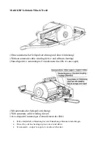
Spannen des Windenkeilriemens:
1.
Abdeckung abnehmen.
2.
Motor abnehmen.
3.
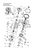
Die vier Schrauben laut Zeichnung Blatt 1 (Abbildung 1) lockern (benötiger Steckschlűssel 13mm).
4.
Schraube (Nr. 2) so lange nach rechts drehen, bis richtige Riemenspannung erreicht ist (Kontrolle mit
der Hand).
5.
Die vier Schrauben (Nr1) wiederum festziehen.
6.
Abdeckung aufsetzen.
Wechseln des Winden-Keilriemens:
Punkt 1 bis 3 gleicher Vorgang wie oben angefűhrt.
4.
Schraube (Nr. 2) nach links drehen, Lagerbock samt Riemensceibezur˝ckscheiben.
5.
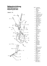
Splinte und Gelenksbolzen am Zugteil und Seilfűhrung entfernen, beide vorn Gerät nehmen.
6.
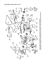
Die vier Muttern und Schrauben (Nr.3) am Verbindungsrahmen des Gerätes (oben und unten) lősen und
entfernen.
7.
Schraube, Sicherungsring und Beilagscheibe (Nr.4) abnehmen.
8.
Gehäusehälfte vom Gerät abziehen.
9.
Riemen auswechseln.
10.
Zusammenbau in umgekehert Reihenfolge. Riemenspannen wie beschrieben.
Tightening the winch V-belt:
1.
Take off the sheeting .
2.
Take off the engine.
3.
Loosen the four screws according to the drawing, (see page 1/gaph.1) in using a socket wrench 13 mm.
4.
Turn screw nr. 2 so long to the right until the correct tension is achieved (Control by hand).
5.
Tighten again the four screws (See nr. 1)
6.
Attach the sheeting.
Changing the winch V-belt:
(1 to 3) Same operations as indicated above
4.
Turn screw nr. 2 to the left, push bearing-stand and V-belt pulley.
5.
Remove split pins and joint bolts of the traction part and the rope quidance, take off both from unit
6.
Loosen the four nuts and screws nr. 3 of the connecting frame of the unit (top and bottom) and remove
them.
7.
Take off: screw, safety ring and washer nr. 4
8.
Pull off the casing-half from unit.
9.
Change the V-belt.
10.
Re-assemble in reversed order and tighten V-belt as described.
Tension de la courroie trapézoidale du treuil:
1.
Retirer la piece de recouvrement.
2.
Retirer le moteur.
3.
Desserrer le 4 vis conformément au plan (Page 1, illust. 1) Cié a pipe nécessaire 13 mm)
4.
Toumer la viso no 2 vers la droite jusqu´a ce que la tension correcte de la courroie soit atteinte (contrôle
a la main).
5.
Serrer de nouveau les 4 vis (no.1)
6.
Remettre la piece de recouvrement.
Changement de la courroi trapézoidale du treuil
Point 1 a 3, comme ci dessus
4.
Tourner la vis (no.2) vers la gauche, pousser le palier support avec la poulie de courroie.
5.
Retirer les goupilles fenues et les boulons d´articulare de la piece de traction et du guide cable
6.
Desserrer et retirer le 4 écrous et vis (no.3) du cadre de liaison de l´appareil (en haut et en bas).
7.
Retirer vis circlip de sureté et rondelle de calage (no.4).
8.
Retirer de l´appareil la moitié du boitier.
9.
Change la courroie.
10.
Remettre en place en ordre inverse. Tendre la couroie suivant la description ci-dessus.
Содержание KBF
Страница 10: ...Multi KBF Seilwinde Winch Treuil...
Страница 11: ...Getriebe mit trommel Gear with drum M canisme d engrenage...
Страница 12: ......


