background image

CLEANING INSTRUCTIONS FOR THE SHOWER CABIN AND DOOR PANEL

A.

Use mild liquid household cleaners to keep metal surface bright and clean. Rinse well and dry

with a clean cloth.

B.

Remove dust with a soft, damp cloth.

C.

Use rubbing alcohol to clean and remove grease, oil, paint, and ink.

D.

Accidental scratches or stains will rarely show. If they do show, they can be easily removed with

a liquid automobile polish.

IMPORTANT

!

Do NOT use abrasive cleaners, scrapers, metal brushes, or any items/products that would

scratch and/or dull surface.

Do NOT allow surface to come into contact with acetone (nail polish remover), dry cleaning

solution, lacquer thinner, gasoline, or any other similar product.

15

MODEL VG06011

OUTSIDE

INSIDE

FIG.16

OUTSIDE

INSIDE

MAINTENANCE INSTRUCTIONS FOR THE SHOWER CABIN AND DOOR PANEL

A.

If you are experiencing water build up in the top portion of the rail, it is recommended to drill

small holes on the top inside portion.  Space holes every 6"-8".  Stay within 3" from the end
of the rail.  [SEE FIG. 16]

Содержание VG06011

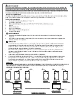
Страница 1: ... These instructions must be observed for safe installation Maintenance and other important non personal injury and non material damage instructions or statements that should be observed It is highly advised to dry fit the unit prior to any installation IMPORTANT SAFETY PRECAUTIONS WARNING The instructions for the following unit is based off of the Vigo brand shower base The instructions can not be...

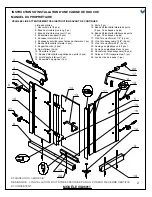
Страница 2: ...seal strip 2pc 1 of each is extra 16 Door bottom seal strip 2pc 1 of each is extra 17 Phillips screw 1 1 8 2pc 18 Hex screw 1 5 8 4pc 19 Phillips screw 3 4 5pc 20 Plastic anchor green 7pc 21 Plastic anchor white 4pc 22 Hex screw cover 16pc 23 Clear PVC shims 1 pack 24 Allen key pack 1 pack 2 1 3 4 6 7 8 9 12 10 11 13 14 MODEL VG06011 15 PLEASE READ INSTRUCTIONS BEFORE PROCEEDING OWNER S MANUAL INS...

Страница 3: ...71 5 8 22 7 8 x70 3 4 10 1 8 x71 5 8 14 1 8 x71 5 8 29 1 4 x71 5 8 21 1 4 x71 5 8 23 5 8 x70 3 4 22 7 8 x70 3 4 33 1 8 x71 5 8 23 5 8 x70 3 4 21 1 4 x71 5 8 34 1 8 34 1 8 36 1 8 36 1 8 30 1 4 38 1 4 32 3 8 40 1 4 34 1 8 46 36 1 8 48 1 8 30 1 4 46 32 3 8 48 1 8 29 1 4 x71 5 8 19 3 4 x70 3 4 9 1 2 x71 5 8 30 1 4 30 1 4 32 3 8 32 3 8 DIM A DIM B MODEL 5 SIDE GLASS PANEL 97003 14 DOOR 97010 6 FRONT GL...

Страница 4: ...h care to prevent injury or material damage Glass on panels and doors is tempered glass and must never be cut to prevent personal injury IMPORTANT Fiberglass or acrylic construction might not be sufficiently strong enough to support the shower door enclosure You should use the wood framing studs from behind the face edge of the stall to provide a secure mounting to the door Apply a bead of silicon...

Страница 5: ... Failure to do so can cause water leakage and bodily harm IMPORTANT To prevent damage to the finish you should protect the shower cabin bottom with a cardboard protector before beginning the installation Ensure that there is sufficient structural support behind the shower wall to hold the weight of the shower door If there is insufficient support then reinforce the shower walls with wooden studs p...

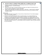
Страница 6: ...nces are correct see page 3 for A and B distances Prior to drilling dry fit everything making sure that everything is straight level and plum Pre drill for sinkers and tap sinkers Cut excess sinker off with hacksaw or sharp blade Dip screws in silicone SEE FIG 2A Screw corner joints and rails down Silicone tops of screws 4 Seal the bottom rail with clear silicone caulk and center its sides to the ...

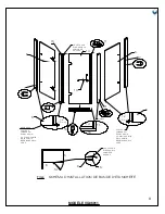
Страница 7: ...lapping the glass and cut at finish of install 6 15 NOTE A MAKE SURE TO LEAVE A GAP OF 3 8 10MM FROM THE BOTTOM OF THE GLASS 7 11 7 16 MAKE SURE TO LEAVE A GAP OF 3 8 10MM FROM THE BOTTOM OF THE GLASS NOTES 1 If the seal strip is not flat and is twisted soak the strip in hot water and press the seal strip back into position 2 Part 15 is reversible and pre cut on top and bottom to fit in proper con...

Страница 8: ...tly Make sure the seal strip 7 is against the wall 6 Mark holes on the wall for the mounting screws 7 Remove the front glass panel Drill holes into the respective marks and insert plastic anchors 21 inside them Not necessary if installing into studs Studs are the preferred means of installation anchors can pull out of the wall causing property damage and bodily harm 8 Replace the front glass panel...

Страница 9: ...nges on the front glass panel 6 SEE FIG 6 Place shim s as needed between the glass and the hinge on the bottom The metal should not rest on the glass SEE FIG 7 3 Screw the hinges to the front glass panel with the hex key supplied INSIDE VIEW FRONT GLASS PANEL 6 CLEAR PVC SHIM FIG 7 11 SEAL STRIP 15 HINGE 10 FRONT GLASS PANEL 6 CLEAR PVC SHIM INSIDE VIEW HINGE 10 21 18 THIN GASKETS 7 8 WALL SIDE DO...

Страница 10: ... The seal 15 may get stuck between the two panels of glass Pull the seal out of the groove using your fingers and nothing sharp making sure not to damage the seal Tighten allen key screws 4 Install the hinges as illustrated SEE FIG 8 Use the hex key supplied 5 Adjust hinge so the gaps are equal at top and bottom and pull door panel away from front panel 6 to allow the door to swing freely without ...

Страница 11: ...l arm 3 to the support assembly 4 on the front fixed panel 6 4 Mark the holes on the wall for the mounting screws for the wall connector 5 Remove the support assembly Drill holes into respective marks and put plastic anchors 20 in them Not necessary if installing into studs 6 Replace wall connector to proper position Screw it in to the wall with 1 1 8 screws 17 7 Slide the structural arms 2 3 into...

Страница 12: ...e door glass panel 14 edge where the door bottom side seal strip 16 is to be installed with rubbing alcohol 2 SEE FIG 11 3 Verify that the soft flange of the seal strip faces toward the inside of the shower cabin before seal strip installation 4 Install the seal strip according to the diagram NOTE If the seal strip is not flat use a hair dryer to apply minimal heat and press the seal strip back in...

Страница 13: ...e perimeter of the bottom rail 4 Apply silicone where the corner joints meet the base rails 5 Apply clear silicone caulk to the seal strip connections of the door bottom seal strip and the door magnetic seal strip SEE FIG 14 J INSTALLING HEX SCREW COVERS 1 Install hex screw covers 22 to the hex screws that mount the hinges wall connectors and glass supports IMPORTANT WAIT 24 HOURS BEFORE USING SHO...

Страница 14: ...MODEL VG06011 14 VG06011 RIGHT DOOR VG06011 LEFT DOOR ...

Страница 15: ...sh IMPORTANT Do NOT use abrasive cleaners scrapers metal brushes or any items products that would scratch and or dull surface Do NOT allow surface to come into contact with acetone nail polish remover dry cleaning solution lacquer thinner gasoline or any other similar product 15 MODEL VG06011 OUTSIDE INSIDE FIG 16 OUTSIDE INSIDE MAINTENANCE INSTRUCTIONS FOR THE SHOWER CABIN AND DOOR PANEL A If you...

Страница 16: ... the installation guide so that VIGO can execute the warranty specified herein If such access is not available all expenses to provide said access will be the responsibility of the owner end user This warranty does not apply to Products that have not been installed or operated in accordance with instructions supplied by VIGO and all applicable rules regulations and legislation pertaining to such i...

Страница 17: ...e les symboles suivants pour indiquer les points importants GUIDE D INSTALLATION DE CABINES DE DOUCHE mortellement en raison d une mauvaise manipulation ou installation du produit Ces instructions IMPORTANT AVERTISSEMENT ATTENTION 1 ...

Страница 18: ...es 2 1 3 4 6 7 8 9 12 10 11 13 14 15 VEUILLEZ LIRE ATTENTIVEMENT CES INSTRUCTIONS AVANT DE CONTINUER INSTRUCTIONS D INSTALLATION D UNE CABINE DE DOUCHE 16 5 17 18 20 19 19 9 21 20 2 23 Cales en PVC transparentes 1 jeu ...

Страница 19: ... 4 x71 5 8 21 1 4 x71 5 8 23 5 8 x70 3 4 22 7 8 x70 3 4 33 1 8 x71 5 8 23 5 8 x70 3 4 21 1 4 x71 5 8 34 1 8 34 1 8 36 1 8 36 1 8 30 1 4 38 1 4 32 3 8 40 1 4 34 1 8 46 36 1 8 48 1 8 30 1 4 46 32 3 8 48 1 8 29 1 4 x71 5 8 19 3 4 x70 3 4 9 1 2 x71 5 8 30 1 4 30 1 4 32 3 8 32 3 8 DIM A DIM B 97003 97010 97004 36 X 36 32 X 48 DIM C AVEC QUINCAILLERIE ET AVEC BAC DE DOUCHE VIGO CORRESPONDANT HAUTEUR 73 ...

Страница 20: ... manquants contactez Vigo Industries au 1 866 591 7792 Niveau Calfeutrage en silicone transparente Couteau tout usage AVERTISSEMENT IMPORTANT bande de silicone entre les parois et le bac de la structure Pour obtenir des performances optimales vous devez installer la porte de douche parfaitement de niveau sur une surface de niveau Sinon il risque d y avoir des fuites d eau et l installation risque ...

Страница 21: ...pliquez correctement la silicone sur les joints du mur et du bac de douche 3 IMPORTANT avec une protection en carton avant de commencer l installation supporter le poids de la porte de douche Si le support est insuffisant renforcez les parois de la FIG 1 ATTENTION DOMMAGES CORPORELS ...

Страница 22: ... BORD EST DOUCHE 19 6 FAITES COULISSER LA INSTALLER LA VIS 3 4 A 1 2 3 Assurez vous que les distances A et B sont correctes cf page 3 pour les distances A et B 4 bac 5 6 FIG 3 CACHE EN ALUMINIUM FIG 3 CAPUCHON DE JOINT D ANGLE ...

Страница 23: ...7 1 2 Cf FIG 4 3 4 dessus pour la remettre en position ...

Страница 24: ...8 FIG 4 13 14 5 CABINE DE DOUCHE CABINE DE DOUCHE AIMANT 3 8 10 mm 5 6 11 16 14 6 15 6 15 LAISSER UN DE LA PARTIE VITRE 7 11 7 16 LAISSER UN DE LA PARTIE VITRE 3 8 10 mm 11 6 14 5 ...

Страница 25: ...isie Cf FIG 1A page 4 Ces 2 3 page 7 4 5 contre le mur 6 Marquez sur le mur l emplacement des vis de montage 7 8 mineures Cf FIG 5A 9 9 FIG 5 JOINTS FINS 7 8 MUR PORTE 6 SUPPORT DE VITRE 8 VUE DU DESSUS MUR LAISSER UN DE LA PARTIE VITRE 15 FIG 5A 8 AJUSTEMENT 10mm 8 ...

Страница 26: ...G 6 JOINTS FINS PORTE 14 PANNEAU AVANT 1 2 3 PANNEAU AVANT CALE EN PVC TRANSPARENTE FIG 7 11 BANDE PANNEAU AVANT CALE EN PVC TRANSPARENTE 21 18 JOINTS FINS 7 8 MUR PORTE 5 DE LA PARTIE VITRE FIG 5B 8 5 7 5 8 ...

Страница 27: ...tallation 3 rainure avec les doigts N utilisez pas d objet pointu car vous risqueriez d endommager le joint 4 hexagonale fournie 5 6 les cales en PVC fournies pour le maintenir fermement en place ouvertures d orifices dans la vitre peuvent varier pendant la production Les cales en PVC corporels AVERTISSEMENT JOINTS FINS JOINT FIN BANDE 11 ...

Страница 28: ...3 1 4 17 1 2 3 4 Marquez sur le mur l emplacement des vis de fixation du raccord mural 5 goujons 6 7 toutes les vis de pression Cf FIG 10 8 20 MUR MUR OU PANNEAU AVANT 2 ou 3 4 MUR OU PANNEAU AVANT 1 FIG 10 NIVEAU 4 ...

Страница 29: ...PANNEAU DE PORTE VIS RONDELLE TRANSPARENTE TUBE BLANC SUPPORT DE VITRE FIG 12 RONDELLE 1 2 Cf FIG 11 3 4 14 11 16 14 11 FIG 11 14 DE LA CABINE DANS LA CABINE 11 16 16 13 ...

Страница 30: ...FIG 13 I APPLICATION DE LA SILICONE 1 2 3 4 5 1 IMPORTANT NE LAISSEZ PORTE 14 11 16 14 16 11 FIG 14 14 ...

Страница 31: ...15 ...

Страница 32: ...PORTE A B C Utilisez de l alcool isopropylique pour nettoyer et enlever la graisse l huile la peinture et l encre D IMPORTANT N utilisez PAS qui rayeraient et ou terniraient la surface NE versez pour peinture d essence ou tout autre produit similaire sur la surface 16 FIG 16 A ...

Страница 33: ...STRIES LLC VIGO en vue d un usage personnel domestique D autres limitations s appliquent en cas d usage commercial constructeur Limitations Limitations commerciales Service de garantie au titre de la garantie 17 ...

Страница 34: ...stas instrucciones cumplirse para no causar lesiones DE SEGURIDAD IMPORTANTES Las instrucciones para la siguiente unidad se basan en la base de ducha Vigo Las instrucciones no pueden utilizarse para otras instalaciones que no sean las de productos Vigo ...

Страница 35: ...ELO VG06011 15 16 5 17 18 20 19 19 9 21 20 2 13 Conjunto de la manilla 1 pieza 14 Puerta 1 pieza 15 Tira selladora lateral de la puerta 2 pieza una adicional de cada una 16 Tira selladora inferior de la puerta 2 pieza una adicional de cada una 17 Tornillo cruciforme crux de 1 1 8 2 piezas 18 Tornillo hexagonal de 1 5 8 4 piezas 19 Tornillo cruciforme crux de 3 4 5 piezas 22 Cubierta de tornillo he...

Страница 36: ...4 10 1 8 x71 5 8 14 1 8 x71 5 8 29 1 4 x71 5 8 21 1 4 x71 5 8 23 5 8 x70 3 4 22 7 8 x70 3 4 33 1 8 x71 5 8 23 5 8 x70 3 4 21 1 4 x71 5 8 29 1 4 x71 5 8 19 3 4 x70 3 4 9 1 2 x71 5 8 22 7 8 22 7 8 23 3 4 23 3 4 19 3 4 22 7 8 22 7 8 23 3 4 23 3 4 19 3 4 36 X 36 32 X 48 32 X 40 36 X 48 32 X 32 MISC MISC 1 CONECTOR DE PARED 2 BRAZO ESTRUCTURAL 4 CONJUNTO DE APOYO 5 PANEL DE VIDRIO LATERAL 7 TIRA SELLAD...

Страница 37: ...e los paneles y las puertas es templado y para evitar lesiones personales nunca debe IMPORTANTE sostener la caja de la puerta de la ducha Debe colocar remaches de madera para marcos en la Aplique un reborde de silicona entre las paredes y la base de la caja materiales EN EL CASO DE LOS MODELOS CON VIDRIO CON ACABADO EN MATE Las secreciones corporales grasosas dejan manchas transparentes en el lado...

Страница 38: ...stener el peso de la puerta Si no hay apoyo suficiente refuerce las paredes de la ducha con remaches de madera antes de instalar la puerta CONSULTE LA FIG 1 ES NECESARIO QUE HAYA JUNTAS ENTRE TODOS LOS PUNTOS DE CONTACTO DEL 5 5 14 6 6 14 FIG 1A IMPORTANTE EL MODELO CON VIDRIO TRANSPARENTE CUENTA CON UNA PUERTA REVERSIBLE QUE PUEDE INSTALARSE DEL LADO DERECHO O DEL IZQUIERDO EL LADO TEXTURADO DE L...

Страница 39: ... en silicona la parte superior de los tornillos 4 lado inferior mire hacia el interior de la ducha CONSULTE LA FIG 3 esquina CONSULTE LA FIG 3 FIG 2 A B FIG 2A 9 12 ESTE BORDE MIRA HACIA EL EXTERIOR DE LA DUCHA ESTE BORDE MIRA HACIA EL INTERIOR DE LA DUCHA 19 DESLICE Y SAQUE LA PARTE SUPERIOR PARA INSTALAR EL TORNILLO DE 3 4 EXTERIOR INTERIOR CUBIERTA DE ALUMINIO FIG 3 INTERIOR EXTERIOR ESQUINA ...

Страница 40: ... del panel fijo delantero nro 6 donde va a instalar la tira selladora lateral de la puerta nro 15 2 CONSULTE LA FIG 4 3 Verifique que el reborde suave de la tira selladora mire hacia el interior de la mampara de ducha antes de instalar la tira selladora NOTAS ...

Страница 41: ...ACIA EL INTERIOR DE LA MAMPARA ESTE LADO DEBE MIRAR HACIA EL INTERIOR DE LA MAMPARA 3 8 10mm 5 6 11 16 14 6 15 6 15 NOTA A DEJAR UNA 3 8 10 MM EN LA PARTE INFERIOR DEL VIDRIO 7 11 7 16 DEJAR UNA 3 8 10 MM EN LA PARTE INFERIOR DEL VIDRIO 3 8 10mm 11 6 14 5 ...

Страница 42: ...que el panel de vidrio delantero Taladre orificios en las marcas respectivas e inserte en ellos 8 los tornillos de 1 5 8 nro 18 des modifications mineures CONSULTE LA FIG 5A 9 Repita los pasos 1 al 8 para el panel de vidrio lateral nro 5 CONSULTE LA FIG 5B 9 MODELO VG06011 21 18 FIG 5 JUNTAS FINAS 7 8 LADO DE LA PARED LADO DE LA PUERTA 6 APOYO DE VIDRIO 8 JUNTA PANEL DE VIDRIO TORNILLO HEXAGONAL V...

Страница 43: ... sobre el vidrio CONSULTE LA FIG 7 3 Atornille las bisagras al panel de vidrio delantero con la llave hexagonal incluida FIG 5B FIG 6 JUNTAS FINAS VISTA DESDE EL INTERIOR PUERTA 14 PANEL DE VIDRIO DELANTERO 6 BISAGRA 8 VISTA INTERIOR PANEL DE VIDRIO DELANTERO 6 POLICLORURO DE VINILO TRANSPARENTE FIG 7 11 TIRA SELLADORA 15 BISAGRA 10 PANEL DE VIDRIO DELANTERO 6 POLICLORURO DE VINILO TRANSPARENTE VI...

Страница 44: ...nal incluida 5 Ajuste la bisagra de manera que las separaciones en la parte superior y la parte inferior sean iguales y aleje el panel de la puerta del panel delantero nro 6 para dejar que la puerta se mueva con libertad sin engancharse con la tira selladora nro 15 6 vinilo impiden que la puerta se combe debido a la gravedad y a su peso Nunca instale la lesiones personales VISTA DESDE EL INTERIOR ...

Страница 45: ...ara ajustar los tornillos CONSULTE LA FIG 9 conjunto de apoyo nro 4 del panel fijo delantero nro 6 4 Marque orificios en la pared para los tornillos de montaje del conector de pared 5 Saque el conjunto de apoyo Taladre orificios en las marcas respectivas e inserte en ellos los tornillos de 1 1 8 nro 17 7 Deslice los brazos estructurales nros 2 y 3 a los conectores de pared nro 1 Ajuste todos los t...

Страница 46: ...NSULTE LA FIG 11 3 Verifique que el reborde suave de la tira selladora mire hacia el interior de la mampara de ducha antes de instalar la tira selladora 14 11 16 14 11 FIG 11 14 11 16 16 13 MODELO VG06011 PANEL DE LA PUERTA MANILLA EXTERIOR MANILLA INTERIOR TORNILLO ARANDELA DE METAL ARANDELA TRANSPARENTE TUBO BLANCO APOYO DE VIDRIO TORNILLO ROSCADO FIG 12 ARANDELA DE METAL EXTERIOR DE LA MAMPARA ...

Страница 47: ...inferior del panel lateral y el 5 Aplique calafate de silicona transparente a las conexiones de la tira selladora inferior con la tira 1 Instale las cubiertas de tornillos hexagonales nro 22 en los tornillos hexagonales que sostienen las bisagras los conectores de pared y los apoyos del vidrio ESPERE 24 HORAS ANTES DE USAR LA DUCHA NO PERMITA QUE EL AGUA TOQUE DIRECTAMENTE LAS TIRAS SELLADORAS 14 ...

Страница 48: ...15 MODELO VG06011 ...

Страница 49: ...rectificado para limpiar y quitar grasa aceite pintura y tinta IMPORTANTE NO utilice raspen la superficie o la opaquen NO permita en seco diluyente para laca gasolina u otro producto similar EXTERIOR INTERIOR FIG 16 EXTERIOR INTERIOR INSTRUCCIONES DE MANTENIMIENTO PARA LA MAMPARA DE LA DUCHA Y EL PANEL DE LA PUERTA ...

Страница 50: ...IGO y durante toda la vida del propietario o usuario final originales final originales y no es transferible a propietarios posteriores Limitaciones manera directo como de manera indirecta dichas instalaciones decir puertas de duchas y lavabos de vidrio por parte de personas sin experiencia puede provocar ruptura del vidrio y por ende lesiones personales o la muerte Limitaciones comerciales ...

Отзывы: