


6
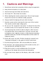
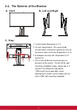
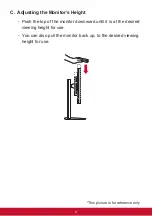
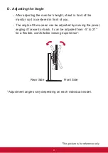
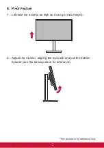
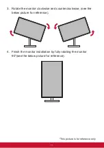
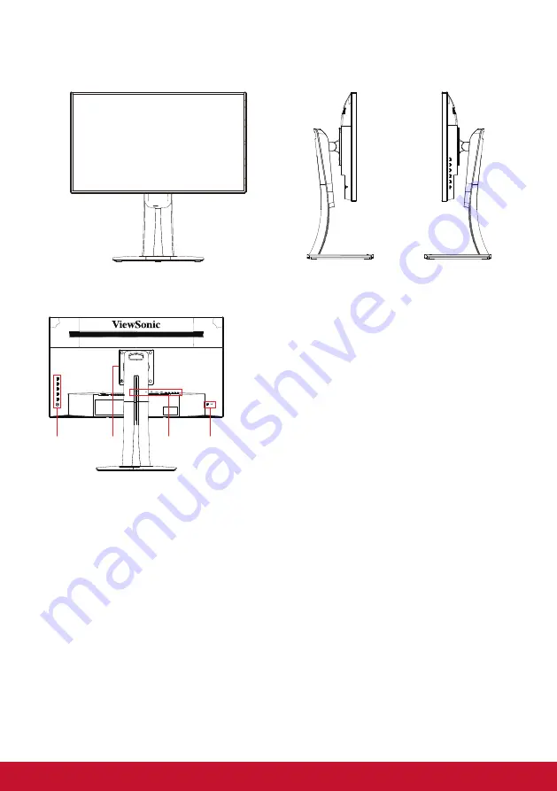
2-2. The Exterior of the Monitor
A. Front
B. Left and Right
C. Rear
2
1
2
4
1
3
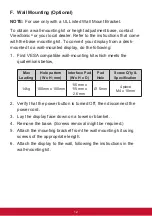
1. Control panel (Expanded in 3-1)
2. I/O port (input/output) This area should
include all I/O connection options, as well as
the power input connector (Expanded in 2-4)
3. Kensington security slot (Expanded in 2-3
section G)
4. This is the VESA wall mounting area on
the back of the moitor*. For the VESA wall
mounting installation steps, please see 2-3
section F for additional instructions.
*VESA wall mount capability varies
depending on model: some models will not
have VESA wall mounting capability.
Содержание VP2768
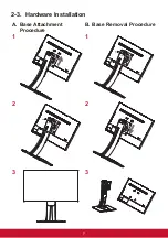
Страница 11: ...7 2 3 Hardware Installation A Base Attachment Procedure B Base Removal Procedure 1 1 2 2 3 3...
Страница 78: ......


