18
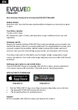
Block Diagram
Pin
Name
Function
1
CT
This pin is to program the frequency of the low frequency timer. By connecting a capacitor to
ground to set the OLP delay time. And this pin can be used for latch mode protection. By pulling
this pin lower than 0.8 V, the controller will be entered latch mode until the AC power-on recycling.
2
COMP
Voltage feedback pin (same as the COMP pin in UC384X), By connecting a photo-coupler to
close the control loop and achieve the regulation. A high quality ceramic capacitor (X7R) is
required for general applications (102pF at least).
3
CS
Current sense pin, connect to sense the MOSFET current
4
GND Ground
5
OUT Gate drive output to drive the external MOSFET
6
VCC Supply voltage pin
7
NC Unconnected Pin
8
HV
Connect this pin to positive terminal of bulk capacitor to provide the startup current for the
controller. When Vcc voltage trips the UVLO(on), this HV loop will be off to save the power loss on
the startup circuit.
Содержание VA2013wm-4
Страница 7: ...7 2 Specification...
Страница 14: ...14 Pin Assignment...
Страница 15: ...15...
Страница 25: ...25 This tool can auto detect the right SCALAR programe speed the process as follow...
Страница 26: ...26...
Страница 27: ...27 When auto detect is finished click Load File then chosse the firmware that you want to update...
Страница 32: ...32 d Unit appears the following Fig writer completed 12 codes for example...
Страница 33: ...33 6 Troubleshooting Flow Chart...
Страница 45: ...45 9 PCB Layout Diagrams 9 1 Main Board...
Страница 46: ...46...
Страница 47: ...47 9 2 Power Board...
Страница 48: ...48...
Страница 49: ...49 9 3 Key Board...
Страница 50: ...50 10 Exploded Diagram and Spare Parts List 10 1 EPL...
Страница 64: ...64 11 Recommended Spare Parts List NA...