21
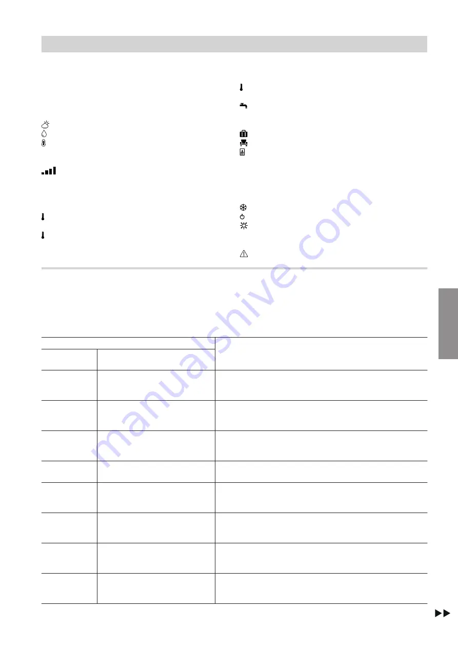
Symbols on the display
These symbols are not always displayed, but appear
subject to the system version and the operating state.
Displays in "Climate info" (home screen)
Current outside temperature
Humidity in the room
Current room temperature
Signal strength
Symbol colour:
■
Red: WiFi
■
Blue: Low Power Radio Status
Temperatures
"Reduced"
Central heating with reduced room tem-
perature
"Normal"
Central heating to standard room tem-
perature
"Comfort"
Central heating to comfort room temper-
ature
DHW temperatures
"Set"
and
"Actual"
Energy saving and comfort functions
"Holiday program"
"Holiday at home"
"Once-only DHW heating"
Symbol colour:
■
Red: Once-only DHW heating is active.
■
Grey: Once-only DHW heating is inactive.
Further operating programs
Frost protection is active.
Standby mode via heat generator control unit
Standby mode via outside temperature
Messages
Fault
Meaning of colours in display
A
and illuminated ring
B
During operation, settings adjustment and in the event
of messages, display
A
and illuminated ring "light
guide"
B
glow in different colours: See the following
table.
Colour
Meaning
Display
A
Illuminated ring "light guide"
B
WH
Blue
Your rooms are heated to the reduced room temperature
"Reduced"
in accordance with the time program: See
WH
Pale yellow
Your rooms are heated to the standard room temperature
"Normal"
in accordance with the time program: See
WH
Orange
Your rooms are heated to the comfort room temperature
"Comfort"
in accordance with the time program: See
WH
Green
Information is being displayed, e.g.
"Domestic Hot Water
heating is on"
.
Blue
Blue
You are in the menu for adjusting the reduced room tempera-
ture setting at the
"Reduced"
temperature level: See
Pale yellow
Pale yellow
You are in the menu for adjusting the standard room temper-
ature setting at the
"Normal"
temperature level: See
Orange
Orange
You are in the menu for adjusting the comfort room tempera-
ture setting at the
"Comfort"
temperature level: See
WH
Red
An activity or message is being displayed.
E.g.
"Connecting to the boiler"
or
"No connection to the
boiler"
Using the remote control
Using the remote control
(cont.)
5839615
Operation
Содержание Vitotrol 300-E
Страница 18: ...18 Fig 7 Installation sequence Inserting the Vitotrol 300 E in the mounting base 5839615 Installation ...
Страница 42: ...42 Certification Certification 5839615 Appendix ...
Страница 45: ...45 5839615 ...
Страница 46: ...46 5839615 ...
Страница 47: ...47 5839615 ...


