


15
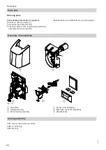
Program sequence during commissioning
0
Start
1. Stage 1
BV2 control cam
2. Stage 2
BV2
TR/STB
A
A'
B
C
D
t1
t40
t3n
t3
TSA
control signals
required input signals
Fig. 13
Note
The output signal at the solenoid valve stage 2
F
is
dependent upon the switch position of the BV2 control
cam of the solenoid valve stage 2 in the servomotor.
A
Start-up begins
B
Point of flame formation
C Burner operating position
D Controlled shutdown
E
Burner motor
F
Solenoid valve stage 2
H
Solenoid valve stage 1
N
Ignition transformer
O
Flame monitor
R
Output controller
t1
Pre-purge time
min. 20 s
t40
Delay time between enabling solenoid valve stage 1
and enabling controller input
approx. 11 s
t3
Pre-ignition time
approx. 20 s
t3n
Post-ignition time begins with flame
(max. until end of "TSA")
max. 5 s
TSA
Start-up safety time
max. 5 s
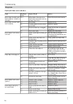
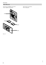
Function and fault indications of the signal indicator (LED)
During standard operation, the operating conditions are indicated by LED signal indicator
A
through colour
codes (see the following table).
After a fault shutdown, the indicator permanently illuminates red. In this condition, the optical fault cause indicator
can be activated (see the following chapter "Burner fault sequence diagram").
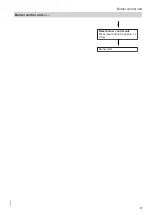
Burner control unit
Burner control unit
5831447