background image

12

5696 675 - 04

Vitocell 300-H, EHA Series Installation 

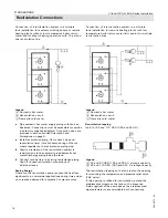
All piping reverse return or use balancing valves.
1. Pipe together boiler (not shown) and tanks as   

  illustrated. Connections must  be accessible for  

  service (use factory supplied adaptors).

2. For boiler water supply temperatures over 203°F   

 (95°C):

  Remove plastic supply and return grommets    

  (grommets are left threaded).

3. Pipe supply line with an elevation and install an  

  automatic air vent at the highest  point.

4. Install boiler sensor in sensor well (see page 10).

5. Insulate piping.

The circulation pump is activated by the sensor / 

operating aquastat and by the control system installed. 

The operating aquastat should be mounted on the tank 

which receives the boiler water supply last.

Viessmann recommends the installation of an additional 

high limit aquastat in the main discharge pipe of the 

DHW system.

This aquastat should be wired in series with the 

operating aquastat and should be set approximately 

9°F (5°C) higher than the operating aquastat.

IMPORTANT

Legend 

A

 Vitocell 300-H  


1

a

” 

*1

B

 Boiler water supply    

2” 

*1

C

 Boiler water return    

3” 

*1

Operating aquastat    

4”

 *1


5” 

*1

*1


Pipe size for boiler supply and return to heat exchanger.


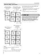
Multiple DHW Tanks 

[only for 92 and 119 USG (350 and 450 L)]

DHW tank battery with 

2 x 357 USG 

(2 x 1350 L)

(2 x triple cell)

WARNING

Install tempering valve(s) to protect against scalding.

WARNING

Do not stack more than three tanks. Stack only tanks of 

identical size.

DHW tank battery with 

357 USG (1350 L )

or

276 USG (900 L)

(triple cell)

Connections

DHW tank battery 

with 184 or 238 USG 

(700 or 900 L) 

(dual cell)

DHW tank battery with

2 x 184 or 2 x 238 USG 

2 x (700 or 2 x 900 L)

(2×dual cell)

Содержание VITOCELL 300-H

Страница 1: ...ure reference IMPORTANT CAUTION The heat transfer medium must be water or other non toxic fluid having a toxicity rating or class of 1 as listed in clinical toxicology of commercial products 5th edition This tank version is not suitable for steam heating applications The pressure of the heat transfer medium must be limited to a max of 30 psig by an approved safety or relief valve Please file in Se...

Страница 2: ...before commencing installation Store documentation near product in a readily accessible location for reference in the future by service personnel For a listing of applicable literature please see section entitled Important Regulatory and Installation Requirements Advice to owner Once the installation work is complete the heating contractor must familiarize the system operator ultimate owner with a...

Страница 3: ...llation clearances for service access 6 Transport and Handling 7 Multiple Tank Set up only for 92 and 119 USG 350 and 450 L 8 Orientation and Dimensions 9 Control Connections 10 Boiler Water Connections Heat Exchanger Connection 11 Individual DHW Tank 11 Multiple DHW Tanks only for 92 and 119 USG 350 and 450 L 12 Steam Heating Side Connections only for 92 and 119 USG 350 and 450 L 13 Individual DH...

Страница 4: ...ot water heating systems There are no user serviceable parts on this equipment Ensure main power supply to equipment the heating system and all external controls has been deactivated Close main oil or gas supply valve Take precautions to avoid accidental activation of power during service work Safety Important Regulatory and Installation Requirements Please carefully read this manual prior to atte...

Страница 5: ...nent information is to be found This symbol indicates that other instructions must be referenced WARNING Indicates an imminently hazardous situation which if not avoided could result in substantial product property damage serious injury or loss of life CAUTION Indicates an imminently hazardous situation which if not avoided may result in minor injury or product property damage IMPORTANT 42 and 53 ...

Страница 6: ...oor If for cleanliness purposes the tank is to be kept off the floor a foundation can be used for each tank or tank battery A minimum clearance of 17 450 mm must be maintained at the back of the tank for the installation of the sensor well and DHW tank temperature sensor Level tank using leveling bolts on tank frame Leveling bolt Storage capacity USG L 42 160 53 200 92 350 119 450 Rear inches mm 1...

Страница 7: ...on ring 6 Pull side panels forward to remove 7 Unscrew top panel Note Only for the 92 USG 350 L Where access to the boiler room is difficult remove the front and side panels unscrew the adjustable feet and turn the DHW tank on it s side This will provide 2 in less width 8 Using a flat piece of wood and a rubber mallet carefully hammer inner front and rear panels off the four corners and remove 9 M...

Страница 8: ...refully pull sensor of the thermometer out of tank cap 6 Pull side panels of top tank forward to remove Multiple Tank Setup only for 92 and 119 USG 350 and 450 L 1 Place top tank on top of bottom tank and align 2 Take packaged M8 bolts drop in holes of top tank support brackets and fasten to bottom tank support brackets 3 Reinstall side panels IMPORTANT Install third tank if applicable in an ident...

Страница 9: ...y F Boiler water return Legend A T P valve and recirculation tapping brass reduction coupling 1 in or 1a in B Domestic hot water C Boiler water supply D Aquastat well brass reduction coupling 1 in b in E Domestic cold water F Boiler water return Storage capacity USG L 42 160 53 200 92 350 119 450 184 700 238 900 357 1350 Number of tanks 1 1 1 1 2 2 3 Layout Connections individual Tanks Heating wat...

Страница 10: ...ol Module not illustrated fully and completely into sensor well Mount aquastat inconspicuously on tank paneling Follow instructions below with regard to sensor and spring clip installation if aquastat is to be mounted remote from the aquastat well 5 Align sensor bulb with spring clip 6 Slide assembly into well 7 The retention spring clip must press the bulb properly to ensure surface contact with ...

Страница 11: ...ith an incline and install componentry as follows 4 Protect all domestic hot water drawpoints from excessive water temperatures via a tempering valve 5 Install DHW tank temperature sensor in sensor well see page 10 6 Insulate piping WARNING The operating aquastat and any secondary high limit aqua stat of the tank must be set such that the DHW temperature inside the tank never exceeds 210 F 99 C In...

Страница 12: ...essmann recommends the installation of an additional high limit aquastat in the main discharge pipe of the DHW system This aquastat should be wired in series with the operating aquastat and should be set approximately 9 F 5 C higher than the operating aquastat IMPORTANT Legend A Vitocell 300 H F 1a 1 B Boiler water supply G 2 1 C Boiler water return H 3 1 E Operating aquastat K 4 1 L 5 1 1 Pipe si...

Страница 13: ...vere burns instantly or death from scalds Children disabled and elderly are at highest risk of being scalded Feel water before bathing or showering Temperature limiting valves are available and must be used where domestic hot water storage tank temperatures exceed 140 F 60 C 1 Pipe steam and condensate lines as illustrated Connections must be accessible for service use factory supplied adaptors 2 ...

Страница 14: ...ith a condensate trap at the end of the steam supply line to each steam valve Install a condensate trap on each heat exchanger outlet before connecting all condensate lines to a common condensate return line or Install a steam valve in the common steam supply line Install a vacuum breaker after the steam valve Install a drain with a condensate trap at the end of the steam supply line to each steam...

Страница 15: ...57 USG 2 x 1350 L 2 x triple cell Ensure that local rules and regulations regarding this type of product have been observed 1 Pipe boiler and tank as illustrated Connections must be accessible for service use factory supplied adaptors 2 Insulate domestic hot water piping and valves IMPORTANT In order to avoid temperature stratification Viessmann recommends the use of a small recirculation pump bet...

Страница 16: ...t water supply B DHW recirculation line C recirculation pump D Spring loaded check valve E Discharge pipe F Pressure and temperature relief valve G Shut off valve H Drain K Domestic cold water supply lines L Back flow preventer M Domestic cold water inlet N Precharged expansion tank required where back flow preventer is installed check local plumbing codes and requirements Connections ...

Страница 17: ... oversized large expansion tank to ensure longer less frequent pump cycles with less severe pressure gradients If possible use flexible piping before and after booster pump to isolate system piping from vibration and shocks WARNING The valve test lever must be operated at least once per year by the owner to ensure that waterways are clear A licensed professional heating contractor shall reinspect ...

Страница 18: ...e 9 Install recirculation pump flow check valve and recirculation timer for shut down during off hours where feasible on the recirculation piping side Gravity circulation of the recirculation system is restricted due to the upward curved domestic hot water discharge piping inside the tank Connect tank battery to existing recirculation piping Cap off unused recirculation connections of individual t...

Страница 19: ...SG 200 L storage capacity C 92 USG 350 L storage capacity D 119 USG 450 L storage capacity Pressure Drop Information Additional Information For start up information refer to the Start up Service Instructions DHW Tank Service 1 File all Parts Lists Operating and Service instructions in the Service Binder 2 Install a protective hanging case near the boiler and store the Service Binder in this locati...

Страница 20: ...5696 675 04 Vitocell 300 H EHA Series Installation Technical information subject to change without notice Printed on environmentally friendly recycled and recyclable paper ...

Отзывы: