Instructions for Use
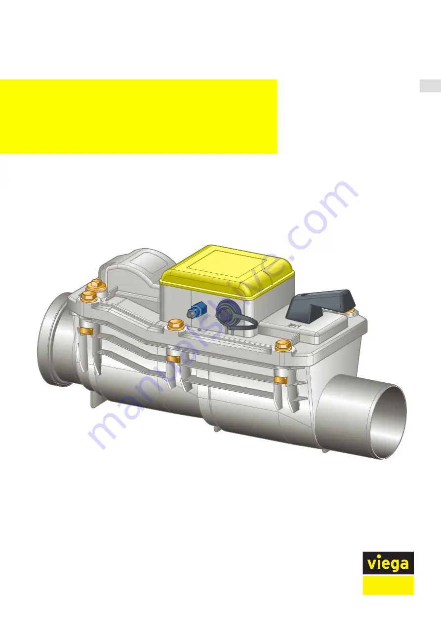
Grundfix Plus Control backflow
trap type 3
for wastewater pipe containing faeces
Model
Year built (from)
4987.41
01/2010
INT
Страница 1: ...Instructions for Use Grundfix Plus Control backflow trap type 3 for wastewater pipe containing faeces Model Year built from 4987 41 01 2010 INT...
Страница 2: ...3 3 Handling 15 3 1 Assembly information 15 3 1 1 Installation dimensions 15 3 2 Assembly 16 3 2 1 Mount base unit 16 3 2 2 Connecting connection cable and pressure hose 16 3 2 3 Connecting the contro...
Страница 3: ...3 6 1 Inspection 33 3 6 2 Maintenance 34 3 6 3 Replacing the rechargeable battery 39 3 7 Disposal 41 Table of contents Grundfix Plus Control backflow trap type 3 3...
Страница 4: ...does not extend to possible operating instructions The installation of Viega products must take place in accordance with the general rules of engineering and the Viega instructions for use 1 2 Labelli...
Страница 5: ...ermany e g DIN DVGW Some passages in the text may refer to technical codes in Europe Germany These should serve as recommendations in the absence of corresponding national regulations The relevant nat...
Страница 6: ...nage points beneath the backflow level DIN 1986 100 Requirements in backflow traps type 3 EN 13564 Regulations from section Application areas Scope Notice Regulations applicable in Ger many Grundfix P...
Страница 7: ...perature of 95 C with pH values of 4 or 10 The backflow trap is suitable for use in drain pipelines made of HT or sewer pipe DN 100 125 or 150 When using other pipes such as e g clay pipes or cast iro...
Страница 8: ...ere is a downward slope to the sewer n the rooms are of lower ranking significance i e neither the inhabi tants health nor major assets would be damaged in case of flooding of the rooms n the system i...
Страница 9: ...1 5 4 2 3 Fig 2 Correct place of installation of the backflow trap 1 Street Backflow level 2 Area safe from backflow Product information Grundfix Plus Control backflow trap type 3 9...
Страница 10: ...ion and installation conditions on page 6 Backflow protections and their control units should be installed in such a way that they are always accessible The backflow sensor reacts at accumulation heig...
Страница 11: ...he backflow trap 1 Measuring funnel 2 Pressure hose 3 connection cable control 4 Motor 5 Pressure switch 6 Emergency lock actuation 7 Lid 8 Casing 9 Emergency lock shutter 10 Motor powered flap Produc...
Страница 12: ...ble 10 Outlet for potential free contacts 2 4 2 Technical data Switching power pack 88 264 VAC 50 60 Hz LCD 20 x 2 with lighting RTC real time clock power reserve 30 days rechargeable battery 12 V 1 2...
Страница 13: ...operation If the pres sure switch registers the backflow of water the motor powered flap is closed the following display appears Back pressure and a signal sounds every 10 seconds The use of the drai...
Страница 14: ...Fig 6 Control elements control unit 1 Menu T1 2 Test T2 3 Reset T3 Product information Grundfix Plus Control backflow trap type 3 14...
Страница 15: ...accumulation heights of 100 mm measured from the upper edge of the base pipe line Therefore when planning the installation heights of the existing floor drains out of which water could flow in the cas...
Страница 16: ...m line up to the middle of the outlet pipe Close the emergency lock position ZU OFF In this way damage from flooding can be avoided before commis sioning Lay the empty pipe from the base unit to the m...
Страница 17: ...n the union nut of the pressure hose slightly using tools Remove the closing cap Plug in the electric plug connection straight NOTICE Make sure that the plug is plugged in straight Connecting the pres...
Страница 18: ...e a cable grip device 3 2 3 Connecting the control DANGER Danger due to electrical current An electric shock can lead to burns and serious injury and even death n Only allow electrical work to be carr...
Страница 19: ...using the quick connec tion Lead the connection cable via the PG screw fitting into the internal space of the control Attach the cable ends n black n red Insert the rechargeable battery Handling Grun...
Страница 20: ...tory fitted rechargeable battery con nection GND 4 red factory fitted rechargeable battery con nection AKKU 5 Green motor connec tion motor 6 Yellow motor connec tion motor 7 signalises back flow R CK...
Страница 21: ...se right INFO On delivery the battery fuse is attached to the inside of the casing with adhesive tape NOTICE Depending on the length of the connection cable a jumper may be required to make a connecti...
Страница 22: ...ds n The use of a safety transformer in accordance with VDE 0551 or DIN EN 60742 is permitted 3 3 Commissioning 3 3 1 Commissioning the control As soon as the mains voltage is connected the control be...
Страница 23: ...switch must be tested using the pressure test Set the emergency lock in ZU OFF position Close the motor powered flap by pressing the button T2 Display Test NRV closed Unscrew the brass plug from the...
Страница 24: ...for 10 minutes by replenishing Observe loss If the loss is greater than 0 5 l check and if required replace the seals on the flaps Set the emergency lock to AUF ON position The water drains away Disp...
Страница 25: ...owered flap open main supply 230 V Backflow protection is assured Operating condition normal operation Chapter 3 4 2 Operating condition normal operation on page 26 Back pressure NRV closed Motor powe...
Страница 26: ...wered emergency operation on page 30 3 4 2 Operating condition normal operation In normal operation control parameters can be entered and information can be called up with the T1 T2 and T3 buttons The...
Страница 27: ...log display and self test Note The adjustment from daylight saving time is carried out manually 5x Event memory Back to event memory Call up events one after another Log display 6x Software vers Back...
Страница 28: ...time Acoustic signals in case of backflow or error are switched off by pressing T1 button once and confirmed with button T3 During normal operation the motor powered flap can be opened and closed by p...
Страница 29: ...buttons have the following functions Function Button Switch off signal Call up Sound off with T1 button and confirm with T3 button Forces motor powered flap to open Keep T3 button pressed for five sec...
Страница 30: ...econds can be switched off using T1 button If the rechargeable battery is fully charged 12 V backflow is ensured for n maximum 24 hours when using the 8 m connection cable n maximum 10 hours when usin...
Страница 31: ...ery n Control unit n Motor motor powered flap with mechanism n Pressure switch If the control unit registers a defect during the daily self test or due to failure of the mains or battery power the rel...
Страница 32: ...e professionals n Check rechargeable battery Recharge able battery fuse n Check cabling Battery error Replace battery Rechargeable battery faulty Operators No safeguarding against back flow in case of...
Страница 33: ...ssure NRV closed Display although there is no back flow occur ring Pressure switch defec tive Operators Positive opening with T3 button keep pressed down for 5 seconds Replace cover 1 The components i...
Страница 34: ...onal n Only use original parts for repair maintenance and extension n Replace defective components do not repair n When using cameras and cleaning devices cleaning spiral high pressure cleaner protect...
Страница 35: ...work the cover must not be cleaned with a high pressure cleaner abrasive cleaning agents blades or similar cleaning equipment To avoid damage only clean casing flap mechanisms and seals with soft brus...
Страница 36: ...of the lid Do not grease the spindle Carefully clean the opening for the pressure switch on the lower side of the cover with a small brush Take out and clean the flaps Check seals if necessary replace...
Страница 37: ...st be greased with silicon grease Install the flaps Place the lid on and screw it down Open the motor powered flap by pressing button T2 Actuate the emergency lock and check it for smooth function Y H...
Страница 38: ...test funnel When the pressure switch is intact the control will report a back flow Display indication Test NRV closed Back pressure NRV closed If necessary a positive opening is possible Press the bu...
Страница 39: ...urns to Normal operation after approx 60 sec onds Alternatively normal operation can be activated using buttons T1 and T3 3 6 3 Replacing the rechargeable battery DANGER Risk of electric shock Replace...
Страница 40: ...on the connection strip 3 black fac tory fitted rechargeable battery con nection GND 4 red factory fitted rechargeable battery con nection AKKU Insert the replacement battery fuse right comprised in...
Страница 41: ...of in accordance with valid national legal requirements Electronic components and batteries must not be put in the domestic waste but must be disposed of appropriately in conformity with the applicabl...
Страница 42: ...Viega GmbH Co KG service technik viega de viega com INT 2021 11 VPN210611...