background image

MNVCHPV_0448

MNVCHPV_0448  7-12-2004  10:03  Pagina 26

Содержание HPV36

Страница 1: ...uctions Operating instructions Manuale istruzioni Custodia per telecamera ed accessori Camera housing and accessories Caisson de protection pour camera video et accessoires Kameragehäuse und Zubehör MNVCHPV_0448 7 12 2004 10 03 Pagina 1 ...

Страница 2: ...N D E X ENGLISH Camera housing and accessories DESCRIPTION 10 Produits et accessoires 10 Entretiens de la vitre et des parties en plastique PC 10 INSTALLATION 10 Ouverture du caisson 10 Installation de la caméra 10 Installation du chauffage 11 Installation de l alimentateur pour camera 11 Installation du ventilateur 11 Système de refroidissement 12 SPÉCIFICATIONS TECHNIQUES 14 Caisson 14 Double to...

Страница 3: ...vo possono essere alimentate solo con tensioni di 12 VDC o 24 VAC Prima di eseguire qualsiasi operazione ricordarsi di togliere tensione al prodotto Prodotti ed accessori La custodia può essere utilizzata a seconda delle configurazioni previste con Tettuccio parasole Kit di riscaldamento Kit di ventilazione Kit di alimentazione Circuito di appoggio con interruttore anti apertura Fig 8 solo version...

Страница 4: ... di appoggio e chiudere la custodia Importante nel circuito c è anche la possibilità di prelevare l alimentazione per una telecamera Alimentando il circuito da una sorgente esterna è necessario prestare attenzione al tipo di tensione utilizzata e adottare a seconda delle esigenze il Kit di alimentazione corretto Installazione dell alimentatore per telecamera Non applicabile nelle custodie munite d...

Страница 5: ...ere compatibile il circuito di appoggio al funzionamento con la tensione di ali mentazione presente Questo connettore deve essere inserito nel suo corrispondente indicato con J5 sul circuito in dotazione 5 Chiudere la custodia Tensione di alimentazione custodia 24 VAC 1 Aprire la custodia come da istruzioni descritte precedentemente 2 Fissare il ventilatore e il relativo circuto di supporto tramit...

Страница 6: ... sistema di raffreddamento sul morsetto indicato con J3 Fig 11 3 Nel circuito c è la possibilità di prelevare l alimentazione per una telecamera sul morsetto indicato con J4 Fig 11 È possibile anche prelevare l alimentazione per il sistema di riscaldamento opzionale morsetto indicato con J2 HEATER Fig 11 Vedi sezione Installazione del riscaldamento 4 Chiudere la custodia operando in maniera invers...

Страница 7: ...in Tensione di ingresso 100 240 VAC Tensione di uscita 12 VDC Corrente fornita 1A Peso 123 g 2 Fig 7 Ingombro 67 2x52 2x40 mm 2 6x2x1 6 in Tensione di ingresso 230 VAC Tensione di uscita 24 VAC Corrente fornita 400 mA Peso 380 g Pressacavi Pressacavo PG9 Ø cavo 5 8 mm 0 2 0 3 in Pressacavo PG11 Ø cavo 5 10 mm 0 2 0 4 in Coppia di serraggio 3 75 Nm Supporti Staffa a parete Dimensioni 80x122x205 mm ...

Страница 8: ...cts and accessories Depending on the configuration provided the housing can be used with Sunshield Heater kit Blower kit Power supply kit Support circuit with tamper switch only 420 mm version Fig 8 Not applicable to cases with installed cooling device Window and plastic cover cleaning PC Surface dirt should be rinsed away with water and then the window cleaned with a neutral soap diluted with wat...

Страница 9: ...ng There are two types of camera power supply depending on requirements One model has an input voltage from 100 VAC to 240 VAC with an output voltage of 12 VDC 1A The other has an input voltage of 230 VAC and an output voltage of 24 VAC 400mA 1 Open the housing as described before 2 Position the camera power supply in the provided seating Fig 4 4A parallel to the support ribs 3 Fix the power suppl...

Страница 10: ...sing the present power supply voltage This connector should be inserted into the correspondent one indicated by J5 on the circuit supplied 5 Close the housing The terminal board marked J4 can be used to take off the main power supply voltage coming from an external source When the circuit is powered by an external source care must be taken to check the type of working voltage and use the correct p...

Страница 11: ...ax 24VAC VDC 0 5A Fig 10 Camera power supply 1 Fig 6 Size 75 5x50x32 3 mm 3x2x1 3 in Input voltage 100 240 VAC Output voltage 12 VDC Output current 1A Weight 123 g 2 Fig 7 Size 67 2x52 2x40 mm 2 6x2x1 6 in Input voltage 230 VAC Output voltage 24 VAC Output current 400 mA Weight 380 g Cable glands Cable gland PG9 Ø cable 5 8 mm 0 2 0 3 in Cable gland PG11 Ø cable 5 10 mm 0 2 0 4 in Fixing tork 3 75...

Страница 12: ...nt de la caméra Les versions de caisson équipées de ce dispositif peuvent exclusivement être alimentées avec des tensions de 12 VDC ou 24 VAC Avant d ef fectuer toute opération il est indispensable de couper l alimentation Produits et accessoires Le caisson peut être utilisé selon les configurations prévues avec Toit pare soleil Kit de chauffage Kit de ventilation Kit d alimentation Circuit d appu...

Страница 13: ... il est aussi possible de prélever l alimentation pour une caméra En alimentant le circuit à partir d une source externe il faut faire attention au type de tension utilisée et adopter selon les exigences le Kit d alimentation correct Installation de l alimentateur pour caméra Non applicable pour les caissons équipés de système pour le refroidissement installé Cette section décrit comment installer...

Страница 14: ...Alimentation 24VAC 1 Ouvrir le caisson en suivant les instructions décrites précédemment 2 Fixer le ventilateur et son circuit de support à l aide du petit étrier de support en angle à l intérieur du corps du caisson en utilisant les vis fournies prévues à cet effet 1 position pour la version en 420 mm et 2 pour celle en 360 mm Fig 5 5A 3 Insérer le connecteur à deux pôles placé en bout de câble d...

Страница 15: ...possible de prélever l alimentation nécessaire au système de chauffage en option borne indiquée comme J2 HEATER Fig 11 Voir section Installation du chauffage 4 Fermer le caisson en procédant selon les indications précédentes mais en sens contraire En cas d alimentation du circuit au moyen d une source externe attention au type de tension utilisée Les versions de caisson équipées de ce dispositif p...

Страница 16: ... 420 mm Max 24VAC VDC 0 5A Fig 10 Alimentateur pour camera 1 Fig 6 Encombrement 75 5x50x32 3 mm 3x2x1 3 in Tension d entrée 100 240 VAC Tension de sortie 12 VDC Courant de sortie 1A Poids 123 g 2 Fig 7 Encombrement 67 2x52 2x40 mm 2 6x2x1 6 in Tension d entrée 230 VAC Tension de sortie 24 VAC Courant de sortie 400 mA Poids 380 g Presse étoupes Presse câble PG9 Ø câble 5 8 mm 0 2 0 3 in Presse câbl...

Страница 17: ...Innentemperatur innerhalb der Betriebsgrenzwer te der Videokamera gehalten werden muß Die mit dieser Einrichtung ausgestatteten Gehäuseversionen können nur mit Spannungswerten von 12 VDC oder 24 VAC versorgt werden Vor allen Eingriffen immer den Netzstecker aus der Steckdose ziehen Produkte und zubehör Das Gehäuse kann je nach Konfiguration ausgestattet werden mit Sonnenschutzdach Heizungs Kit Lüf...

Страница 18: ...am Kabelende an die vorgesehene Stelle der Trägerschaltung gekenn zeichnet durch die Aufschrift J2 Heater Fig 9 10 11 e 12 6 Jetzt den internen Auflageschlitten wieder positionieren und das Gehäuse schließen Die Schaltung bietet daneben die Möglichkeit die Stromversorgung für eine Kamera abzugreifen Speist man den Schaltkreis aus einer externen Quelle ist darauf zu achten welcher Spannungstyp benu...

Страница 19: ... mit geeigneten Anschlüssen geliefert um den Auflageschaltkreis mit dem Betrieb der vorhandenen Versorgungsspannung kompatibel zu machen 5 Dieser Stecker muß an der vorgesehenen mit J5 bezeichneten Stelle auf dem beiliegenden Schaltkreis eingefügt werden 6 Das Schutzgehäuse schließen Betriebsspannung 24 VAC 1 Öffnen Sie das Gehäuse wie vorstehend beschrieben 2 Befestigen Sie den Lüfter und seine T...

Страница 20: ... an der Klemme J3 vornehmen Fig 11 3 Im Schaltkreis besteht die Möglichkeit die Speisung für eine Videokamera an der Klemme mit der Bezeichnung J4 abzugreifen Fig 11 Man kann auch die Speisung für die als Extra erhältliche Beheizungsanlage abgreifen die Klemme ist mit J2 HEATER gekennzeichnet Fig 11 Siehe hierzu den Abschnitt zur Installation der Beheizungsanlage 4 Das Gehäuse wird in der umgekehr...

Страница 21: ...für 420 mm Version Max 24VCA VDC 0 5A Fig 10 Netzteil für Kamera 1 Fig 6 Ausmaße 75 5x50x32 3 mm 3x2x1 3 in Eingangsspannung 100 240 VAC Ausgangsspannung 12 VDC Augangsstrom 1A Gewicht 123 g 2 Fig 7 Ausmaße 67 2x52 2x40 mm 2 6x2x1 6 in Eingangsspannung 230 VAC Ausgangsspannung 24 VAC Augangsstrom 400mA Gewicht 380 g Kabelschellen Kabelschelle PG9 Ø Kabel 5 8 mm 0 2 0 3 in Kabelschelle PG11 Ø Kabel...

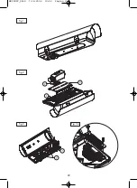
Страница 22: ...20 Fig 1 Fig 2 Fig 3 Fig 3A MNVCHPV_0448 7 12 2004 10 03 Pagina 20 ...

Страница 23: ...21 Fig 4 Fig 4A Fig 5 Fig 5A Fig 6 Fig 7 MNVCHPV_0448 7 12 2004 10 03 Pagina 21 ...

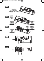
Страница 24: ...RE BLOWER VENTILATEUR LÜFTER RISCALDAMENTO HEATER CHAUFFAGE HEIZUNG ALIMENTATORE POWER SUPPLY ALIMENTATEUR NETZTEIL Fig 9 VENTILATORE BLOWER VENTILATEUR LÜFTER ALIMENTATORE POWER SUPPLY ALIMENTATEUR NETZTEIL RISCALDAMENTO HEATER CHAUFFAGE HEIZUNG Fig 10 Fig 11 Fig 12 MNVCHPV_0448 7 12 2004 10 03 Pagina 22 ...

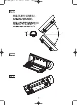
Страница 25: ...ON MAXI SUR L AXE TRANSVERSAL 0 MAXIMALE DREHUNG AUF DER QUERACHSE 0 MASSIMA INCLINAZIONE SULL ASSE LONGITUDINALE 45 MAXIMAL INCLINATION ON THE LONGITUDINAL AXIS 45 INCLINATION MAXI SUL L AXE LONGITUDINAL 45 MAXIMALE NEIGUNG AUF DER LÄNGSACHSE 45 Fig 14 Fig 15 Fig 13 MNVCHPV_0448 7 12 2004 10 03 Pagina 23 ...

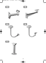
Страница 26: ...24 Fig 16 Fig 17 Fig 18 Fig 19 Fig 20 MNVCHPV_0448 7 12 2004 10 03 Pagina 24 ...

Страница 27: ... jede Haftung für eventuelle Schäden ab die aufgrund unsachgemäßer Anwendung der in diesem Handbuch erwähnten Geräte entstanden ist Ferner behält er sich das Recht vor den Inhalt ohne Vorkündigung abzuändern Die Dokumentation in diesem Handbuch wurde sorgfältig ausgeführt und überprüft dennoch kann der Hersteller keine Haftung für die Verwendung übernehmen Dasselbe gilt für jede Person oder Gesell...

Страница 28: ...MNVCHPV_0448 MNVCHPV_0448 7 12 2004 10 03 Pagina 26 ...

Отзывы: