background image

VP220D Installation Guide

    |    

6

430751-081 (Rev. 8/21) Copyright 2021 VideoProtects Incorporated. All rights reserved.

Step 4 –

 Connect power supply

There are three ways to provide power to the camera:

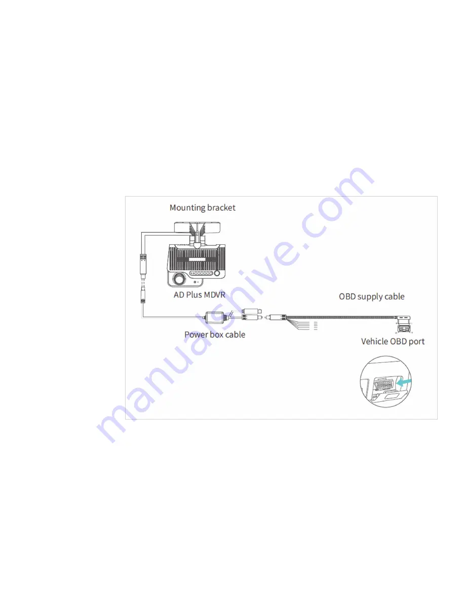
1)  Quick plug-in OBD-II power cable adapter (ordered separately)

  If using the OBD-II power supply connection, plug the power box cable into the camera.  

Then, connect the OBD-II quick plug to the power box cable. Route the assembled cable  

up under the headliner, and down the A pillar into the dashboard area near the OBD-II port  

on the vehicle. Plug the OBD-II quick connector into an available OBD-II port. Secure the  

cables under the dashboard with zip ties.


NOTE:

 An OBD-II T harness (ordered separately) will be required to provide multiple  

OBD-II ports for connecting the camera and a GO device.

2)  Quick plug-in 9 pin power cable adapter (ordered separately)


If using the 9-pin power supply connection, plug the power box cable into the camera.  

Then, connect the 9-pin quick plug to the power box cable. Route the assembled cable 

up under the headliner, and down the A pillar into the dashboard area near the 9-pin port  

on the vehicle. Plug the 9-pin quick connector into an available 9-pin port.


NOTE:

 A 9-pin T harness (ordered separately) might be required to provide the appropriate 

ports for connecting the camera and a GO device.

Содержание VP220D

Страница 1: ...430751 081 Rev 8 21 Copyright 2021 VideoProtects Incorporated All rights reserved VP220D Installation Guide...

Страница 2: ...VP220D Installation Guide 2 430751 081 Rev 8 21 Copyright 2021 VideoProtects Incorporated All rights reserved Table of Contents Camera Features 3 Quick Installation Guide 4 8 Status Bar Key 9...

Страница 3: ...VP220D Installation Guide 3 430751 081 Rev 8 21 Copyright 2021 VideoProtects Incorporated All rights reserved Camera Features...

Страница 4: ...ot interfere with the driver s view from the rearview mirror The ideal installation area is shown in the figure below 1 Clean the interior and exterior of the glass in the target installation area wit...

Страница 5: ...to the bracket with the front side facing inward with the teeth on the left side of the bracket engaged with those on the left inner side of the camera Tighten the bracket bolt clockwise with a PH2 c...

Страница 6: ...nector into an available OBD II port Secure the cables under the dashboard with zip ties NOTE An OBD II T harness ordered separately will be required to provide multiple OBD II ports for connecting th...

Страница 7: ...ated All rights reserved 3 Direct wiring cut in included in camera kit If the mode of power supply connection through discrete wire cut in is adopted connect POWER ACC GND with the power cable of the...

Страница 8: ...r on camera and validate operation 1 Ensure that all power cables are connected and that the GO device is installed per GeoTab s instructions see GeoTab for GO device installation steps 2 Turn on the...

Страница 9: ...onnection normal light off Location connection abnormal solid red light 4 NET Cellular Network connection normal light off Cellular Network connection abnormal solid red light 5 WIFI Client mode light...

Страница 10: ...430723 081...

Отзывы: