background image


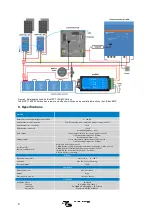
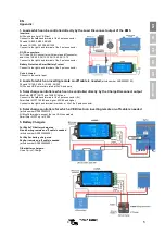
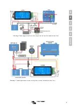
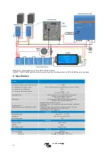
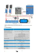
Figure 4: Solar application with two MPPT 150/85 CAN-bus 

The MPPT 150/85 CAN-bus has a remote on-off port which can be be controlled directly by the VE.Bus BMS 


8. Specifications 


miniBMS 


Normal operating Input voltage range (Vbat) 

8 – 70V DC 

Current draw, normal operation 

2.7 mA (excluding Load output and Charger output current) 

Current draw, low cell voltage 

2mA 

Current draw, remote off 

1,5 mA 

Load output 

Normally high (Vbat – 0.1V) 

Source current limit: 1A (not short circuit protected) 

Sink current: 0A (output free floating) 

Charger output 

Normally high (Vbat –o.6V) 

Source current limit: 10mA (short circuit protected) 

Sink current: 0A (output free floating) 

System on/off: 
Remote L and Remote H 

Use modes of the system on-off: 
a. ON when the L and H terminal are interconnected (switch or relay contact) 
b. ON when the L terminal is pulled to battery minus (V< 3.5V) 
c. ON when the H terminal is high (2.9V < V

H

 < Vbat) 

d. OFF in all other conditions 

GENERAL 

Operating temperature 

-20 to +50°C          0 - 120°F 

Humidity  

Max. 95% (non-condensing) 

Protection grade 

IP20 

ENCLOSURE 

Material and colour 

ABS, matt black 

Weight 

0.1kg 

Dimensions (h x w x d) 

106 x 42 x 23mm 

STANDARDS 

Standards: Safety 
                       Emission 
                       Immunity 
                       Automotive 

EN 60950 

EN 61000-6-3, EN 55014-1 

EN 61000-6-2, EN 61000-6-1, EN 55014-2 

Regulation UN/ECE-R10 Rev.4 


Содержание miniBMS

Страница 1: ...Manual EN Handleiding NL Manuel FR Anleitung DE Manual ES Appendix miniBMS ...

Страница 2: ......

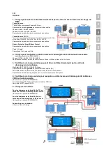
Страница 3: ...ad ON blue Load output high cell voltage 2 8V adjustable on the battery Temp or OVP red Charger output free floating due to cell over temperature 50 C cell under temperature 5 C or cell over voltage 2 Safety instructions Installation must strictly follow the national safety regulations in compliance with the enclosure installation creepage clearance casualty markings and segregation requirements o...

Страница 4: ... DC DC converter 3 5 Charging the LiFePO battery with a battery charger Battery charging must be reduced or stopped in case of imminent cell over voltage or over temperature The Charge Disconnect output of the VE Bus BMS can be used for this purpose The Charge Disconnect is normally high equal to battery voltage and switches to open circuit state in case of imminent cell over voltage Battery charg...

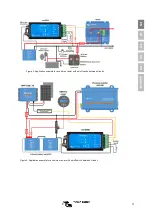
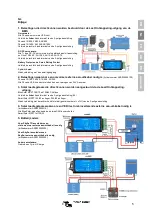
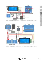
Страница 5: ...3 EN NL FR DE ES Appendix Figure 2 Application example for a vehicle or boat with on off switch between H and L Figure 3 Application example for a vehicle or boat with on off switch between H and L ...

Страница 6: ...ally high Vbat o 6V Source current limit 10mA short circuit protected Sink current 0A output free floating System on off Remote L and Remote H Use modes of the system on off a ON when the L and H terminal are interconnected switch or relay contact b ON when the L terminal is pulled to battery minus V 3 5V c ON when the H terminal is high 2 9V VH Vbat d OFF in all other conditions GENERAL Operating...

Страница 7: ...le is needed article number ASS030550100 Phoenix 12 180 24 180 12 250 24 350 All Phoenix VE Bus inverters rated at 3kVA and more 3 Solar charge controllers which can be controlled directly by the Charge Disconnect output BlueSolar MPPT 150 70 and 150 80 CAN bus Connect to the left hand terminal of the 2 pole connector B SmartSolar MPPT 150 45 and higher 250 60 and higher Connect to the right hand ...

Страница 8: ......

Страница 9: ...anningsbereik 8 tot 70V DC LED indicatoren Laad ON blauw Laadvermogen hoog celspanning 2 8V instelbaar op de batterij Temp of OVP rood Lader uitgang vrij zwevend door cel over temperatuur 50 C cel onder temperatuur 5 C of cel overspanning 2 Veiligheidsinstructies De installatie moet strikt voldoen aan de nationale veiligheidsvoorschriften in overeenstemming met de vereisten voor behuizing systeem ...

Страница 10: ...een omvormer of een DC DC omvormer 3 5 De LiFePO batterij laden met een batterijlader Opladen van de batterij moet worden verminderd of gestopt in het geval van dreigende overbelasting van de cel of te hoge temperatuur Hiervoor kan de Laden Ontkoppeling uitgang van de VE Bus BMS worden gebruikt De Laden Ontkoppeling is normaal gesproken hoog gelijk aan de batterijspanning en schakelt over op open ...

Страница 11: ...FR DE ES Appendix Afbeelding 2 Toepassingsvoorbeeld voor een voertuig of boot met aan uitschakelaar tussen H en L Afbeelding 3 Toepassingsvoorbeeld voor een voertuig of boot met aan uitschakelaar tussen H en L ...

Страница 12: ...ang Normaal hoog Vbat 0 6V Bronstroomlimiet 10mA beveiligd tegen kortsluiting Zinkstroom 0A uitgang vrij zwevend Systeem aan uit Afstandsbediening L en Afstandsbediening H Gebruik modi van het aan uit systeem a AAN wanneer de L en H terminal onderling zijn verbonden schakelaar of relaiscontact b AAN wanneer de L terminal richting de batterij minus V 3 5V gaat c AAN wanneer de H terminal vol is 2 9...

Страница 13: ...uit kabel nodig is Artikelnummer ASS030550100 Phoenix 12 180 24 180 12 250 24 350 Alle Phoenix VE Bus omvormers hebben een vermogen van 3kVA en meer 3 Solar laadregelaars die direct kunnen worden aangestuurd via de Laad Ontkoppeling uitgang BlueSolar MPPT 150 70 en 150 80 CAN bus Verbind de linker hand terminal van de 2 polige aansluiting B SmartSolar MPPT 150 45 en hoger 250 60 en hoger Maak verb...

Страница 14: ......

Страница 15: ...n de 8 à 70 VCC Indicateurs LED Charge ALLUMÉE bleu Sortie de charge élevée tension de cellule 2 8 V réglable sur la batterie Temp ou OVP rouge Sortie du chargeur flottante en raison de la surchauffe des cellules 50 ºC de la température insuffisante des cellules 5 ºC ou de la surtension des cellules 2 Consignes de sécurité L installation doit respecter strictement les réglementations international...

Страница 16: ...isseur CC CC 3 5 Charger la batterie LiFePO avec un chargeur de batterie La charge de la batterie doit être réduite ou arrêtée en cas de surtension ou surchauffe imminente des cellules La sortie de déconnexion de charge du VE Bus BMS peut être utilisée à cette fin La déconnexion de charge est normalement élevée égale à la tension de la batterie et elle commute à l état de circuit ouvert en cas de ...

Страница 17: ...stration 2 exemple d application pour un véhicule ou un bateau avec un interrupteur d allumage arrêt entre H et L Illustration 3 exemple d application pour un véhicule ou un bateau avec un interrupteur d allumage arrêt entre H et L ...

Страница 18: ...ortie du chargeur Normalement élevée Vbat 0 6 V Limite de courant de source 10 mA protégée contre les courts circuits Courant absorbé 0 A sortie flottante Allumage arrêt du système L à distance et H à distance Modes d utilisation de l allumage arrêt à distance a ON si les bornes L et H sont connectées entre elles interrupteur ou contact de relais b ON si la borne L est raccordée à la borne négativ...

Страница 19: ...80 12 250 24 350 La puissance nominale de tous les convertisseurs Phoenix VE Bus s élève à 3 kVA et plus 3 Contrôleurs de charge solaires pouvant être contrôlés directement par la sortie de déconnexion de la charge BlueSolar MPPT 150 70 et 150 80 CAN bus Raccordez la borne de gauche au connecteur à deux pôles B SmartSolar MPPT 150 45 et version supérieure 250 60 et version supérieure Raccordez la ...

Страница 20: ......

Страница 21: ...t AN blau Lastausgang hoch Zellspannung 2 8 V an der Batterie regulierbar Temp oder OVP rot Ausgang Ladegerät potentialfrei aufgrund der Zell Übertemperatur 50 C Zell Untertemperatur 5 C oder Zell Überspannung 2 Sicherheitshinweise Bei der Installation müssen die nationalen Sicherheitsbestimmungen bezüglich des Gehäuses der Installation der Luft und Kriechstrecken des Unfallschutzes der Markierung...

Страница 22: ...gskondensator wie einem Wechselrichter oder einem DC DC Konverter einschalten 3 5 Laden der LiFePO Batterie mit einem Batterieladegerät Das Laden der Batterie muss reduziert oder angehalten werden wenn eine Zell Überspannung oder Über Temperatur unmittelbar bevorsteht Der Ausgang Charge Disconnect des VE Bus BMS kann zu diesem Zweck verwendet werden Der Ausgang Charge Disconnect ist normalerweise ...

Страница 23: ...Appendix Abbildung 2 Anwendungsbeispiel für ein Fahrzeug bzw ein Boot mit einem Ein Aus Schalter zwischen H und L Abbildung 3 Anwendungsbeispiel für ein Fahrzeug bzw ein Boot mit einem Ein Aus Schalter zwischen H und L ...

Страница 24: ...HIGH Vbat 0 6 V Quellstrombegrenzung 10 mA kurzschlussfest Senkstrom 0 A Ausgang potentialfrei System ein aus Remote L und Remote H Verwenden Modi des Ein Aus Schalters des Systems a EIN wenn die Anschlüsse L und H miteinander verbunden sind Schalter oder Relais Kontakt b EIN wenn der Anschluss L auf den Minuspol der Batterie gezogen wird V 3 5 V c EIN wenn der Anschluss H HIGH ist 2 9 V VH Vbat d...

Страница 25: ...r ASS030550100 Phoenix 12 180 24 180 12 250 24 350 Alle Phoenix VE Bus Wechselrichter mit einer Mindestnennscheinleistung von 3 kVA 3 Solar Lade Regler die sich direkt über den Ausgang Charge disconnect steuern lassen BlueSolar MPPT 150 70 und 150 80 CAN bus An den linken Anschluss des zweipoligen Steckers B anschließen SmartSolar MPPT 150 45 und höher 250 60 und höher An den rechten Anschluss mar...

Страница 26: ......

Страница 27: ...r en la batería Protección frente a sobretensión o temperatura rojo Salida del cargador flotante debido a sobretemperatura de la celda 50 C baja temperatura de la celda 5 C o sobretensión de la celda 2 Instrucciones de seguridad La instalación debe cumplir estrictamente las normas de seguridad nacionales en cuanto a los requisitos de recinto instalación línea de fuga distancias de seguridad accide...

Страница 28: ...mo un inversor o un convertidor CC CC 3 5 Carga de la batería LiFePO con un cargador de batería La carga de la batería debe ser reducida o detenida en caso de sobretensión o sobretemperatura inminente en las celdas Con este propósito se puede utilizar la salida de desconexión de carga del BMS VE Bus La Desconexión de Carga es normalmente alta igual a la tensión de la batería y cambia a estado de c...

Страница 29: ... FR DE ES Appendix Figura 2 Ejemplo de aplicación para un vehículo o barco con un interruptor on off entre H y L Figura 3 Ejemplo de aplicación para un vehículo o barco con un interruptor on off entre H y L ...

Страница 30: ...da del cargador Normalmente alta Vbat 0 6 V Límite de corriente de entrada 10 mA con protección frente a cortocircuitos Corriente de disipación 0A salida de flotación libre On off del sistema L remoto y H remoto Modos de uso del on off del sistema a ON cuando los terminales L y H están interconectados interruptor o contacto de relé b ON cuando el terminal L se conecta al negativo de la batería V 3...

Страница 31: ... nº ASS030550100 Phoenix 12 180 24 180 12 250 24 350 Todos los inversores Phoenix VE Bus de 3kVA o más 3 Controladores de carga solar que pueden controlarse directamente con la salida de Desconexión de Carga BlueSolar MPPT 150 70 y 150 80 CAN bus Conecte al terminal del lado izquierdo del conector de dos polos B SmartSolar MPPT 150 45 y superiores 250 60 y superiores Conecte al terminal del lado d...

Страница 32: ......

Страница 33: ...stributor Serial number Version 01 Date 18 October 2018 Victron Energy B V De Paal 35 1351 JG Almere PO Box 50016 1305 AA Almere The Netherlands General phone 31 0 36 535 97 00 E mail sales victronenergy com www victronenergy com ...

Отзывы: