


ESS7/EST4/ESL4/ELC4
- 23 -
SECTION 3
10. Apply
only
Loctite® #222 threadlocker to the Outlet Connection
[27]
threads. Install the
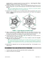
Outlet Connection into the Body and torque to 15 ft-lbs.
11. At this point, thoroughly blow out the Body assembly with pressurized oil-free air or dry
nitrogen to insure it is completely free of chips and debris.
12. Install the Seat Guide
[4]
into the Body – it should slip in freely. Note its orientation when
installing – the angled end faces down, into the Body.
TIP: Make sure the Seat Guide is installed straight. It should appear flat and level in
the body (not tilted at an angle). To ease installation, use a small Screwdriver or
Punch that can fit through the center hole of the Seat Guide. Slip the Seat Guide
onto the Screwdriver, then, while holding the Seat Guide up on the shank, position
the end of the Screwdriver approximately centered down inside the body (below the
assembly location of the Seat Guide). Then, simply drop the Seat Guide, letting it
slide down the Screwdriver and fall into position.
13.
Preassemble the seat components:
Push the Friction Damper
[5]
into the Gland
[6]
,
and then slip the Valve Spring
[7]
, Gland and Friction Damper onto the shaft of the Seat
Assembly
[21]
.
TIP: The Friction Damper should have enough tension to hold the Gland and the
Valve Spring in position on the shaft of the Seat Assembly. If there appears to be no
tension (if the parts just seem to want to fall off), then there may be a problem with
your Friction Damper, or the Friction Damper may not be firmly pushed up in place
inside the Gland.
Then install the preassembled seat components into the Regulator Body – with the
Friction Damper and Gland fitting down into the cup shape of the Seat Guide.
14. Install the new O-Ring
[8]
onto the Nozzle
[9]
, fitting it in place over the small ridge on the
bottom of the Nozzle.
DO NOT
use lubricant on the O-Ring. Install the Nozzle/O-Ring
into the Regulator Body and torque to 20 ft-lbs.
15.
Preassemble the Adjusting Mechanism:
Apply CHRISTO-LUBE® #129 Lubricant to
the entire length of the threads of the Drive Screw
[13]
, and screw the Guide Bushing
[12]
onto the Drive Screw (by hand) all the way up until it stops (do not over-tighten!).
Note that this is a
left hand thread
. Next, apply
only
Loctite® #222 to the threads of the
#10-32 Screw
[10]
, and install the Screw and Washer
[11]
into the Drive Screw –
tightening until snug.
TIP: Make sure you’ve got the Drive Screw oriented correctly – the Screw and
Washer you just installed should be in the end that’s opposite the square flats.
16. Diaphragm Assembly:
EST4, ESL4 and ESS7 models:
Install the Diaphragm Assembly
[2]
into the Body.
Note that the Diaphragm centers itself in a recessed pocket in the top of the Body.
ESS7 200 PSIG Delivery models:
Install the Diaphragm Assembly
[2]
into the Body.
Note that the Diaphragm centers itself in a recessed pocket in the top of the Body. Then
install the Backup Ring
[2A]
over the Diaphragm Assembly. Insure it is oriented as
shown in the Exploded View detail on Page 1.
ELC4 Models:
Apply a very light coat of CHRISTO-LUBE® #129 Lubricant to the
Diaphragm O-Ring
[2D]
and install it into the groove in the top of the Body. Next, place
the Diaphragm Assembly
[2C]
on top of it. Note that the Diaphragm centers itself in a
recessed pocket in the top of the Body. Lastly, install the Diaphragm Shim
[2B]
on top of
the Diaphragm Assembly. It sits loosely on top of the Diaphragm Assembly, centered on
the Body.