


ESS3/ESS4
- 8 -
SECTION 1
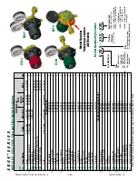
Regulator Max.
Delivery Pressure
Mating Relief
Valve (Nominal)
Recommended
Blow-off Pressure
15 PSIG
30 PSIG
27 to 33 PSIG
40 PSIG
60 PSIG
55 to 66 PSIG
125 PSIG
200 PSIG
180 to 220 PSIG
200 PSIG
400 PSIG
360 to 440 PSIG
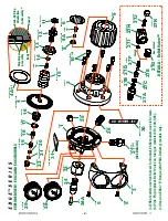
9. When all testing is completed, bleed pressure off the Relief Valve. Install the Cap Nut
[27K]
on the Vented Relief Valve.
10. Apply
either
Teflon® tape or Loctite® #222 to the Relief Valve (or Pipe Plug)
[27]
threads. Install the Relief Valve (or Pipe Plug) into the Body and torque to 15 ft-lbs.
11. Apply
only
Loctite® #222 threadlocker to the Outlet Connection
[26]
threads. Install the
Outlet Connection into the Body and torque to 15 ft-lbs.
12. At this point, thoroughly blow out the Body assembly with pressurized oil-free air or dry
nitrogen to insure it is completely free of chips and debris.
13. Install the Bottom Guide
[22]
into the Body – it should slip in freely. Note its orientation
when installing – the cupped end with the hex on it should face up.
14.
Preassemble the seat components:
Push the Friction Damper
[21]
into the Gland
[20]
,
and then slip the Valve Spring
[19]
, Gland and Friction Damper onto the shaft of the Seat
Assembly
[18]
.
TIP: The Friction Damper should have enough tension to hold the Gland and the
Valve Spring in position on the shaft of the Seat Assembly. If there appears to be no
tension (if the parts just seem to want to fall off), then there may be a problem with
your Friction Damper, or the Friction Damper may not be firmly pushed up in place
inside the Gland.
Then install the preassembled seat components into the Regulator Body – with the
Friction Damper and Gland fitting down into the cup shape of the Bottom Guide.
15. Install the new O-Ring
[17]
onto the Nozzle
[16]
, taking care to guide it carefully over the
Nozzle threads to avoid nicks or tears.
DO NOT
use lubricant on the O-Ring. Install the
Nozzle/O-Ring into the Regulator Body and torque to 15 ft-lbs. Note that 15 ft-lbs is the
same recommended torque for the Inlet Connection Swivel, so as you torque down the
Nozzle,
you’re also finish-tightening the Inlet Swivel to the correct torque value
.
TIP: Watch the Inlet Swivel while you torque down the Nozzle. If the Swivel is turning
with the Body, then you need to tighten the Inlet Nut tighter on the Inlet Swivel
Assembly Plug. You want to be sure that the 15 ft-lbs torque is being applied to both
the Nozzle threads and the Inlet Swivel threads.
16.
Preassemble the Adjusting Mechanism:
Apply CHRISTO-LUBE® #129 Lubricant to
the entire length of the threads of the Drive Screw
[12]
, and screw the Guide Bushing
[13]
onto the Drive Screw (by hand) all the way up until it stops (do not over tighten!).
Note that this is a
left hand thread
. Next, apply
only
Loctite® #222 to the threads of the
#10-32 Screw
[7]
, and install the Screw and Washer
[14]
into the Drive Screw –
tightening until snug.
TIP: Make sure you’ve got the Drive Screw oriented correctly – the Screw and
Washer you just installed should be in the end that’s opposite the square flats.
17. Install the Diaphragm Assembly
[4]
, Adjusting Spring
[15]
, preassembled Adjusting
Mechanism and Thrust Washer
[11]
onto the Regulator Body. Note that the Diaphragm