


CAMERA
i
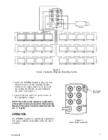
Figure 2
System Connection Diagram, Branching System
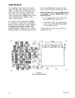
5. Secure the
module in place by loos-
ening the screw on the retaining bracket,
located at the upper right rear of the mod-
ule, sliding the bracket up and tightening
the screw. See Figure 3.
6. Connect the line cord to a power source of
the appropriate voltage.
NOTE: The bezel on the module is protected by
a thin plastic covering to prevent scratches during
shipping. The plastic should be removed when the
unit is installed.
OPERATION
The
requires no operational adjustments.
The power indicator lamp lights when the unit is
energized.
RETAINING
BRACKET
Figure 3
Rear Panel Assembly
X125-1089
3