


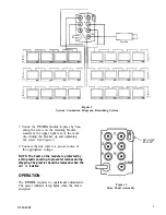


If an operating failure occurs in the system,
inspect all cables and connections. Check the
camera to ensure that it is functioning prop-
erly. Check each successive connection for
the presence of a good video signal. If nec-
essary, interchange the
output connec-
tors to determine if the amplifier, or the
branch wiring is faulty.
The solid-state unit is designed for
free operation in normal room environments.
Repairs should be attempted by only qualified
personnel in an adequately equipped facility.
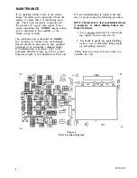
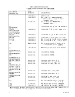
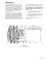
If troubleshooting is necessary, refer to the
Schematic Diagram (Figure
Parts Location
Diagram (Figure 5) and Replacement Parts List.
If local troubleshooting is required, the unit
may be opened using the following procedure.
NOTE: The removal
of four
countersunk screws
is necessary to remove shielding. Remove only
those
four screws.
1. Use a
screwdriver to remove the
top, bottom, and two side screws.
2. Use hands to gently pry apart shielding
walls at rear of unit while lifting shield
up and pulling rearward.
Follow these two steps in reverse order to re-
assemble the unit.
FUSE
1
t
u
0
Figure 4
Parts Location Diagram
-0
Tl
R32
+
3
J14
+
X125-1089