37
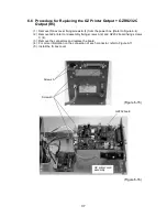
6-6 Procedure for Replacing the GZ Printer GZRS232C
Output (R5)
(1) Remove IS box cover fixing screws B (4) from the power box. (Refer to Figure 6-4)
(2) Remove GZ printer cord assembly fixing screws A (2) and GZ232 board fixing screws
C (4).
(3) Remove the connectors and replace the board.
(4) For more information on the connection of each connector, refer to Figure 6-17.
(5) Install the IS box cover.
(Figure 6-16)
Screws A
(Figure 6-15)
Screws C
GZ232 board
GZ printer cord
assembly


