background image




GZ II Series 


Service Manual 


SHINKO DENSHI CO., LTD. 

Содержание GZ II Series

Страница 1: ...GZ II Series Service Manual SHINKO DENSHI CO LTD...

Страница 2: ...res 18 5 1 Procedure for Replacing the Mechanical Sensor Assembly 18 5 2 Procedure for Replacing the Tuning Fork Assembly 21 5 3 Procedure for Replacing the GZDSP 2 Board 24 5 4 Procedure for Replacin...

Страница 3: ...1 Chapter 1 Appearance 1 1 Appearance of the Round Pan Type 1000 2000 g 1 2 Appearance of the Square Pan Type 6000 15 kg Figure 1 1 Figure 1 2...

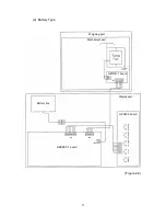
Страница 4: ...the Electric Components 2 1 Entire Wiring Diagram 1 Power Box Type Figure 2 1 Weighing part Mechanical part Power box GZOSC 1 board Display part GZLF board GZDSP 2 board GZSW 2 board ON OFF Print Lim...

Страница 5: ...3 2 Battery Type Figure 2 2 Weighing part Mechanical part GZOSC 1 board Display part Battery box GZSW 2 board GZBDSP 1 board ON OFF Print Limit Add Set Switch Zero Tare...

Страница 6: ...ical unit has failed Replace the mechanical unit Replace the tuning fork assembly Is the power supply voltage in the circuit normal The GZDSP 2 GZBDSP 1 board has failed The GZLF board has failed Repl...

Страница 7: ...mechanical unit 6 The balance is being affected by wind or vibration etc 6 Check the area around the balance The displayed value is unstable Poor repeatability The zero point changes 7 The GZOSC 1 bo...

Страница 8: ...ts the reference weights are less than 50 of the weighing capacity 1 Set reference weights so that they weigh 50 or more of the weighing capacity is displayed 1 During semi auto span adjustment adjust...

Страница 9: ...the pan base and pan are properly in place Make sure no foreign objects are present under the pan or pan base Make sure the right kind of pan is used Make sure the balance is placed on a stable surfa...

Страница 10: ...e value is shared between Type B and Type D 1 Power supply voltage check CN4 11 to 13 V Type B 6 00 to 10 32 V 2 In circuit power supply voltage check CN2 4 88 to 5 12 V CN2 4 88 to 5 12 V 3 Signal wa...

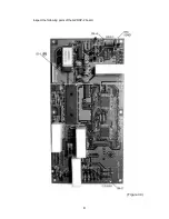
Страница 11: ...9 Inspect the following parts of the GZDSP 2 board Figure 3 3...

Страница 12: ...10 Inspect the following parts of the GZBDSP 1 board Figure 3 4 Connected to the battery box...

Страница 13: ...Place a load that is half the weighing capacity and check the amplitudes and phase differences of CH 1 and CH 2 Amplitude P P CH 1 150 mV or more average 750 mV CH 2 700 mV or more average 3 5 V Figur...

Страница 14: ...g capacity The weight of standard test weights is less than half of the weighing capacity The error of the displayed weight exceeds 1 Press the ON OFF key to turn the display on Press and hold until t...

Страница 15: ...ce is horizontal 3 Adjust the corner error according to the following corner error adjustment table Figure 4 2 To the GZDSP board Corner error adjusting bolt A Corner error adjusting bolt B Figure 4 1...

Страница 16: ...djustment procedure The coefficient data has changed due to static electricity or noise Enter the coefficient data See the coefficient label on the Figure 4 3 Span adjustment Performance check Poor li...

Страница 17: ...wing procedure 1 Location of the coefficient data label 2 How to read the data sheet Data sheet Figure 4 3 After replacing the mechanical unit put the data sheet for the new unit on top of the old dat...

Страница 18: ...ime is pressed after that the rightmost digit changes from to and After the highest digit is selected the rightmost digit moves to the left every time is pressed Ex Pressing again causes a number to a...

Страница 19: ...the balance enters weight display mode Press and hold until the display change from to Check that nothing is on the pan Then press while pressing and release the keys at the same time blinks and the...

Страница 20: ...n and pan base 2 Remove the unit cover mounting screws A 4 with a Phillips head screwdriver 3 Remove the unit cover Figure 5 1 2 How to Install the Unit Cover 1 Reassemble the unit cover taking care n...

Страница 21: ...e GZOSC 1 board 4 Remove the mechanical unit mounting nuts B 3 with a 7 mm box nutdriver 5 Remove the mechanical unit from the chassis Take care not to catch anything under the mechanical unit Figure...

Страница 22: ...s B 2 Solder the tuning fork assembly cord to the GZOSC 1 board 3 Check the position of the stopper to the sub link guide If misaligned readjust the position by loosening screws C 2 4 Place the unit c...

Страница 23: ...21 5 2 Procedure for Replacing the Tuning Fork Assembly The tuning fork assembly has failed Replace the tuning fork assembly Linearity adjustment Performance check...

Страница 24: ...shape and that there is no dust or foreign substances 2 While pushing the guide link upward until the guide link touches the stopper temporarily secure screws A 3 While lightly pushing the guide link...

Страница 25: ...gauge 0 05 t between the stopper plate and the guide link insert the jig rod into the hole provided on the edge of the stopper plate and secure the mounting screws while holding the stopper plate 3 R...

Страница 26: ...rocedure for Replacing the GZDSP 2 Board The GZDSP 2 board has failed Replace the GZDSP 2 board Use the board that has been set to fit each model Reenter the coefficient data Span adjustment Performan...

Страница 27: ...board connector to the CN2 of a new GZDSP 2 board 2 Temporarily secure the GZDSP 2 board mounting screws C 5 and after adjusting the inclination of the LCD tube secure the screws 3 Connect the connec...

Страница 28: ...2 Temporarily secure GZBDSP 1 board mounting screws C 4 and the hexagonal spacer and after adjusting the inclination of the LCD tube secure the screws and the spacer 3 Secure the clamp for the red and...

Страница 29: ...ove the PC bracket mounting screws A 2 5 Remove the GZOSC 1 board mounting screws B 2 Figure 5 12 2 How to Install the GZOSC 1 Board 1 Install a new GZOSC 1 board with mounting screws B 2 2 Solder the...

Страница 30: ...mounting screws A 2 metal connector mounting screws B 4 and ground wire mounting screw C 1 Figure 5 13 2 How to Install the GZLF Board 1 Install a new GZLF board with screws A B and C Be careful of t...

Страница 31: ...barrier terminals 3 Loosen the screw of one side of the fixture and replace the insulating barrier 4 Connect barrier communication cord L to terminal 3P and the barrier power cord to 2P No 10 brown N...

Страница 32: ...connector CN7 of the GZPS board 3 Remove fixing screws C from the GZJP board and replace it 4 Connect the CN3 of the GZJP board to the CN7 of the GZPS board and connect the RS232 power cords to the C...

Страница 33: ...GZ printer cord assembly fixing screws A 2 3 Remove the nylon clamp and the connector and replace the assembly 4 For more information on connector connection refer to Figure 6 8 5 Install the IS box...

Страница 34: ...iagram Figure 6 8 GZ printer cord assembly AE476 GZ232 power cord Power cable Insulating barrier Barrier communication cord L Red Black Barrier power cord GZPS board ZB GZJP board GZJP board direct co...

Страница 35: ...crews B 4 from the power box Refer to Figure 6 4 2 Remove GZ232 board fixing screws A 4 3 Remove the connectors and replace the board 4 For more information on the connection of each connector refer t...

Страница 36: ...GZJP power cord GZ232 board GZ232 power cord Power cable Insulating barrier Barrier communication cord L Barrier power cord GZPS board ZB GZJP board GZJP board direct connect cord GZ232 board direct c...

Страница 37: ...rews B 4 from the power box Refer to Figure 6 4 2 Remove GZ422 board fixing screws A 4 3 Remove the connectors and replace the board 4 For more information on the connection of each connector refer to...

Страница 38: ...GZJP power cord GZ422 board GZ232 power cord Power cable Insulating barrier Barrier communication cord L Barrier power cord GZPS board ZB GZJP board GZJP board direct connect cord GZ232 board direct c...

Страница 39: ...er to Figure 6 4 2 Remove GZ printer cord assembly fixing screws A 2 and GZ232 board fixing screws C 4 3 Remove the connectors and replace the board 4 For more information on the connection of each co...

Страница 40: ...rinter cord assembly AE476 GZ232 power cord Power cable Insulating barrier Barrier communication cord L Red Black Barrier power cord GZPS board ZB GZJP board GZJP board direct connect cord GZ232 board...

Страница 41: ...6 4 2 Remove GZJP board fixing screw A 1 GZLM board fixing screws C 4 and GZ TARE assembly fixing screws D 2 3 Remove the connectors and replace the board 4 For more information on the connection of...

Страница 42: ...wer cord GZLM board GZ232 power cord Power cable Insulating barrier Barrier communication cord L Red Black Barrier power cord GZPS board ZB GZJP board GZJP board direct connect cord GZ232 board direct...

Страница 43: ...igure 6 4 2 Remove GZJP board fixing screw A 1 GZLM board fixing screws C 4 and GZ232 board fixing screws D 4 3 Remove the connectors and replace the board 4 For more information on the connection of...

Страница 44: ...nect cord GZJP power cord GZJP board direct connect cord GZ232 power cord GZ232 power cord GZ232 board GZJP board GZLM board GZ232 board direct connect cord Power cable Insulating barrier Barrier comm...

Страница 45: ...oard fixing screw D 1 and GZBCD board fixing screws E 4 For more information on how to install the GZ printer cord assembly refer to Figure 6 6 3 Remove the connectors and replace the board 4 For more...

Страница 46: ...g barrier Barrier communication cord L Red Black Barrier power cord GZPS board ZB GZ232 power cord GZJP board GZJP board direct connect cord GZ232 board direct connect cord GZ232 power cord GZJP power...

Отзывы: