INPUT
OUT
OUT
DC P
ASS
LinkStar
™
PWR
ALM
COU
SAT
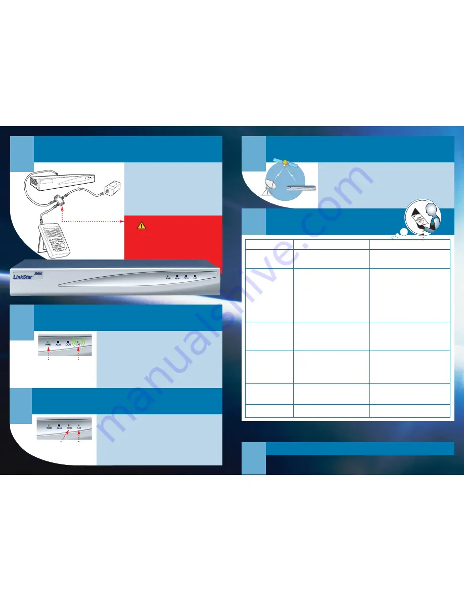
LNB
2-way splitter
with one DC pass
Spectrum Analyzer
RCST
Connect IFL cable to RF IN
on spectrum analyzer
or peaking meter
L-band
950-1750 MHz
Connect IFL cable to RX IN
on rear of RCST
4.
Antenna Pointing
5.
Receive Synchronization
5a.
Turn OFF power to RCST (and unplug External Power Supply, if used).
5b.
Disconnect cables from spectrum analyzer and DC block/splitter.
5c.
Connect the Rx IFL cable from the LNB to the RCST Rx In. DO NOT connect the Tx IFL
cable from the BUC to Tx Out.
5d.
Turn ON power to RCST (and plug in power cord for External Power Supply, if used).
5e.
Check SAT LED:
Blinking slowly indicates Rx sync.
Blinking quickly indicates NCR sync (1.0.8 and later). If Rx sync is not acquired,
refer to Troubleshooting, Item B in this QuickStart Guide.
6.
Transmit Synchronization
6a.
Turn OFF power to RCST (and unplug the External Power Supply, if used).
6b.
Connect Tx IFL cable from BUC to RCST Tx Out.
6c.
Turn ON power to RCST. ODU LED should be steady ON. After 5 minutes, SAT LED
should be steady ON to indicate Tx sync. If SAT LED is OFF or blinking, refer to
Troubleshooting, Item D in this QuickStart Guide.
Verify ODU LED
is ON Green,
indicating ODU
Power
Verify SAT LED
is ON Green,
indicating transmit
synchronization
Verify PWR
LED is ON
Verify SAT LED is
blinking Green,
indicating receive/NCR
synchronization
7.
Final Check
7a.
Contact the Hub operator to verify:
- RCST status (
ps, tcmp
commands).
- Ping from Hub to RCST.
- Software version (
Imep
command).
7b.
If the ping fails, refer to Troubleshooting, Item F in this QuickStart Guide.
If the ping was successful, congratulations! You have
installed your RCST!
How to Contact Us
web
www.viasat.com/skynet
C A U T I O N ! !
DC VOLTAGE IS PRESENT ON THE IFL CABLES
To prevent damage to the spectrum analyzer, be sure to use
a splitter that blocks the DC to the spectrum analyzer.
Reorder Information:
Item No. 1004772 Rev.001
HUB
4a.
Power OFF RCST (and External Power Supply, if used).
4b.
Connect cables, spectrum analyzer (or peaking meter), and
DC block/splitter, as shown.
4c.
Turn ON power to RCST (and plug in External Power Supply, if used).
4d.
Point antenna to elevation and azimuth specified for satellite.
4e.
Perform azimuth sweeps at different elevations until satellite beacon is
found. Call the satellite operator to verify the polarization adjustment.
If satellite beacon is not found, refer to Troubleshooting, Item B in this
QuickStart Guide.
24/7 customer support
+1 (888)272-7232 (U.S.)
+1 (760)476-2600 (Outside U.S.)
Troubleshooting
Problem
Things You Should Check
For more detail, refer to the
LinkStar RCST
Installation Guide (Item No. ING00076)
, Section...
A.
RCST does not power on
B.
No Receive Synchronization
C.
High Receive BER
D.
No Transmit Synchronization
E.
High RCST Transmit BER
F.
No IP Traffic
1. AC power wired to 110/220 VAC.
2. Blown fuse.
3. Bad AC power cable.
If the RCST still does not power ON, replace the RCST.
1. Boot parameters:
• TDM frequency.
• TDM symbol rate.
2. IFL cable connectors.
3. Receive IFL cable type, length.
4. LNB frequency.
5. TDM signal level.
6. Noise level.
7. Interfering signal.
8. Obstructions.
9. Antenna polarization.
10. Antenna pointing.
1. Weather conditions.
2. TDM signal level.
3. Cable attenuation.
4. Antenna polarization.
5. Antenna pointing.
6. Interference.
1. Boot parameters:
• Terminal ID.
• Population ID.
• Control PID.
• Tx power.
2. Transmit IFL Cable type, length.
3. BUC output power.
1. Weather conditions.
2. TDMA signal level at GCU.
3. BUC output power.
4. Antenna polarization.
1. Allocated bandwidth.
2. IP Status.
(SAT LED is not blinking.)
(LED is not solid
steady green.)
13.3 RCST Power ON Failure
“
“
13.5.5 TDM Frequency and Symbol Rate
“
“
13.5.3 Receive IFL Cable
“
13.5.2 LNB
13.5.1 Receive TDM Signal
13.5.4 Antenna
“
“
“
“
13.6 Receive TDM BER
“
“
“
“
“
13.7.2 RCST Boot Parameters
“
“
“
“
13.7.4 TDMA Transmit Level
“
13.8 RCST Transmit BER
“
“
“
13.9 Traffic Test
“
?
© 2003 ViaSat, Inc. All rights reserved.
LinkStar
™
is a trademark of ViaSat, Inc.
ViaSat Proprietary.
No part of this document may be reproduced or transmitted in any form or by any means,
electronic or mechanical, for any purpose, without the express written permission of ViaSat, Inc.


