VIA Technologies Video Wall Mini Скачать руководство пользователя страница 42


Video Wall Mini User Manual

Video Wall Mini User Manual

Video Wall Mini User Manual

Video Wall Mini User Manual    


30


5.2.


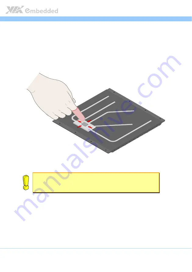
How to reinstall the top cover 

 
Step 1

Step 1

Step 1

Step 1    

On the inner side of the top cover, spread the thermal grease evenly on the 
center area of the heat pipe plate before reinstalling the top cover. Using a 
plastic protector, use your finger to spread the grease.  


Figure 

Figure 

Figure 

Figure 30

30

30

30: 

: Spreading thermal 

Spreading thermal 

Spreading thermal 

Spreading thermal grease

grease

grease

grease    


Reminder

Reminder

Reminder

Reminder::::        

Every time the user takes off the top cover, the amount of thermal grease (between the heat pipe plate 
and CPU heatsink) may decrease. Therefore, adding a small amount of thermal grease is advisable. Use 
the thermal grease (in tube syringe) provided in the package. 


Содержание Video Wall Mini

Страница 1: ......

Страница 2: ...1 03 10312014 140100 USER MANUAL Video Wall Mini Fanless and Slim size system with 4 display HDMI support...

Страница 3: ...cts described in this manual at any time without prior notice Regulatory Compliance FCC FCC FCC FCC A Radio Frequency A Radio Frequency A Radio Frequency A Radio Frequency Interference Statement Inter...

Страница 4: ...ch a way that people cannot step on it Always unplug the power cord before inserting any add on card or module If any of the following situations arises get the equipment checked by authorized service...

Страница 5: ...1 3Q10A1 3Q10A1 1 x Video Wall Mini system unit 1 x Power cord 180 cm Japan Type 1 x Power adaptor 12V 8 5A 102W 1 x Power cable 4 hole DC In jack 2 x HDMI cable strap holder 4 x SATA SSD screws 4 x M...

Страница 6: ...rals Peripherals Peripherals Peripherals Model Number Model Number Model Number Model Number Description Description Description Description EMIO 1533 00A2 802 11 b g n Wireless LAN USB Module EMIO 15...

Страница 7: ...Descriptions and Functionality External I O Pin Descriptions and Functionality External I O Pin Descriptions and Functionality 11 11 11 11 2 1 Front Panel I O 11 2 1 1 DC In Jack Power Input 11 2 1 2...

Страница 8: ...tall 3G 3 5G module and antenna 38 5 9 How to install WLAN USB module and antenna 41 6 6 6 6 BIOS Setup Ut BIOS Setup Ut BIOS Setup Ut BIOS Setup Utility ility ility ility 45 45 45 45 6 1 Entering the...

Страница 9: ...4 Discard Changes and Reset 72 6 9 5 Save Changes 72 6 9 6 Discard Changes 72 6 9 7 Save as User Defaults 72 6 9 8 Restore User Defaults 72 6 9 9 Launch EFI Shell from file system device 72 7 7 7 7 So...

Страница 10: ...t diagram 17 Figure 18 COM connector diagram 18 Figure 19 LPC connector diagram 19 Figure 20 VGA pin header diagram 20 Figure 21 SPI pin header diagram 21 Figure 22 System temperature sensor pin heade...

Страница 11: ...en 51 Figure 53 Illustration of SATA Configuration screen 52 Figure 54 Illustration of USB Configuration 53 Figure 55 Illustration of F71869 Super IO Configuration screen 55 Figure 56 Illustration of...

Страница 12: ...pinout 15 Table 6 DIO connector pinout 16 Table 7 USB 2 0 port pinout 17 Table 8 COM connector pinout 18 Table 9 LPC connector pinout 19 Table 10 VGA pin header pinout 20 Table 11 SPI pin header pinou...

Страница 13: ...LAN USB WiFi connectivity which can be supported through one on board USB pin header In addition it supports mini PCIe card slots for mSATA storage and 3G 3 5G connectivity with SIM card slot The Vide...

Страница 14: ...he onboard mini PCIe card slot enables the Video Wall Mini to have a flexible storage mSATA module 1 1 6 Wide Range of Operating Temperatures The Video Wall Mini carries a qualified thermal performanc...

Страница 15: ...me 645 640 DX11 graphics processor with 2D 3D video acceleration with MPEG 2 VC 1 and H 264 video decoder Display Memory Display Memory Display Memory Display Memory Optimized Shared Memory Architectu...

Страница 16: ...ort 1 x DIO connector D sub 9 pin Storage Storage Storage Storage Serial ATA Serial ATA Serial ATA Serial ATA Built in one SSD hard drive bay for 2 5 inch SATA SSD mSATA mSATA mSATA mSATA Built in one...

Страница 17: ...n connector support 8 bit GPIO Two USB 2 0 ports One COM D sub 9 pin connector support RS 232 RS 422 RS 485 Two antenna holes for WLAN antenna and 3G 3 5 antenna Onboard I O Onboard I O Onboard I O On...

Страница 18: ...ding during operation with with with with 2 5 2 5 2 5 2 5 SATA SATA SATA SATA SSD SSD SSD SSD 5Grms IEC 60068 2 64 random 5 500Hz 1hr axis Shock during operation with Shock during operation with Shock...

Страница 19: ...1 1 1 Front side layout label Front side layout label Front side layout label Front side layout label Figure Figure Figure Figure 2 2 2 2 Right side layout label Right side layout label Right side la...

Страница 20: ...al Video Wall Mini User Manual Video Wall Mini User Manual Video Wall Mini User Manual 8 Figure Figure Figure Figure 4 4 4 4 Bottom side layout label Bottom side layout label Bottom side layout label...

Страница 21: ...ll Mini User Manual 9 1 4 Dimensions Figure Figure Figure Figure 5 5 5 5 Front Front Front Front v v v view iew iew iew dim dim dim dimensions ensions ensions ensions Figure Figure Figure Figure 6 6 6...

Страница 22: ...ual Video Wall Mini User Manual Video Wall Mini User Manual Video Wall Mini User Manual 10 Figure Figure Figure Figure 7 7 7 7 Bottom Bottom Bottom Bottom v v v view d iew d iew d iew dimensions imens...

Страница 23: ...In Jack Power Input The Video Wall Mini comes with a 4 hole DC In jack that carries 12V DC external power input Figure Figure Figure Figure 8 8 8 8 DC DC DC DC In In In In jack jack jack jack diagram...

Страница 24: ...vices which utilize a high definition video playback The pinout of the HDMI port is shown below Figure Figure Figure Figure 10 10 10 10 HDMI HDMI HDMI HDMI port diagram port diagram port diagram port...

Страница 25: ...deo Wall Mini that indicate the status of the system Power LED flashes in green and indicates system s power status SATA SSD LED flashes in red and indicates hard drive storage activity for 2 5 SATA S...

Страница 26: ...D3 8 LAN1_TD3 Table Table Table Table 3 3 3 3 RJ RJ RJ RJ 45 LAN port 45 LAN port 45 LAN port 45 LAN port pinout pinout pinout pinout The LAN port has two individual LED indicators located on the fron...

Страница 27: ...ith two USB 3 0 ports The USB 3 0 port has a maximum data transfer rate up to 5 Gbps and offers a backward compatible with previous USB 2 0 specifications It gives complete Plug and Play and hot swap...

Страница 28: ...d WLAN LED and WLAN LED and WLAN LED indi indi indi indicator cator cator cator 2 2 2 Digital I O Connector The Video Wall Mini system is equipped with 8 bit Digital I O GPIO connector D sub 9 pin whi...

Страница 29: ...Rev 2 0 The USB 2 0 pinout is shown below Figure Figure Figure Figure 17 17 17 17 USB USB USB USB 2 0 2 0 2 0 2 0 port diagram port diagram port diagram port diagram USB USB USB USB port port port por...

Страница 30: ...y adjusting the BIOS setup items However the default setting of COM connector is the standard RS 232 The pinout of the COM connector is shown below Figure Figure Figure Figure 18 18 18 18 COM COM COM...

Страница 31: ...ll Mini system s mainboard 3 1 LPC Connector The Video Wall Mini has one LPC connector for debugging purpose The connector is labeled as JLPC1 The pinout of the connector is shown below Figure Figure...

Страница 32: ...A1 The pinout of the VGA pin header is shown below Figure Figure Figure Figure 20 20 20 20 VGA pin header diagram VGA pin header diagram VGA pin header diagram VGA pin header diagram Pin Pin Pin Pin S...

Страница 33: ...OM The SPI pin header is labeled as SPI1 The pinout of the SPI pin header is shown below Figure Figure Figure Figure 21 21 21 21 SPI pin header diagram SPI pin header diagram SPI pin header diagram SP...

Страница 34: ...r is labeled as J7 The pinout of the temperature sensor pin header is shown below Figure Figure Figure Figure 22 22 22 22 System System System System t t t temperature emperature emperature emperature...

Страница 35: ...n Short Short Short Short and Open Open Open Open The pins are Short Short Short Short when a jumper cap is placed on the pair of pins The pins are O O O Open pen pen pen if the jumper cap is removed...

Страница 36: ...as JRST1 Figure Figure Figure Figure 24 24 24 24 System System System System r r r reset jumper eset jumper eset jumper eset jumper diagram diagram diagram diagram Setting Setting Setting Setting Pin...

Страница 37: ...gure 25 25 25 25 Res Res Res Reset CMOS RAM jumper et CMOS RAM jumper et CMOS RAM jumper et CMOS RAM jumper diagram diagram diagram diagram Setting Setting Setting Setting Pin 1 Pin 1 Pin 1 Pin 1 Pin...

Страница 38: ...26 26 26 26 SPI SPI SPI SPI a a a address select jumper ddress select jumper ddress select jumper ddress select jumper diagram diagram diagram diagram Setting Setting Setting Setting Pin 1 Pin 1 Pin 1...

Страница 39: ...2 and 3 afterwards The default setting is on pins 2 and 3 Figure Figure Figure Figure 27 27 27 27 Re Re Re Recovery BIOS covery BIOS covery BIOS covery BIOS jumper diagram jumper diagram jumper diagr...

Страница 40: ...D VSUSVDD VDD VDD VDD m m m mode ode ode ode select jumper diagram select jumper diagram select jumper diagram select jumper diagram Setting Setting Setting Setting Pin 1 Pin 1 Pin 1 Pin 1 Pin 2 Pin 2...

Страница 41: ...provides the information about hardware installation procedures 5 1 How to remove the top cover Step 1 Step 1 Step 1 Step 1 Remove the top screws x4 of front and rear plates and remove the eight screw...

Страница 42: ...he top cover Using a plastic protector use your finger to spread the grease Figure Figure Figure Figure 30 30 30 30 Spreading thermal Spreading thermal Spreading thermal Spreading thermal grease greas...

Страница 43: ...the chassis Figu Figu Figu Figure re re re 31 31 31 31 Aligning the top cover Aligning the top cover Aligning the top cover Aligning the top cover Step Step Step Step 3 3 3 3 Secure the top cover with...

Страница 44: ...et Align the notch on the memory module with the notch on the SODIMM socket Step Step Step Step 2 2 2 2 Gently insert the DDR3 memory module into the SODIMM socket at a 30 angle Figure Figure Figure F...

Страница 45: ...re Figure Figure Figure 34 34 34 34 Disengaging the SODIMM locking clips Disengaging the SODIMM locking clips Disengaging the SODIMM locking clips Disengaging the SODIMM locking clips Step 2 Step 2 St...

Страница 46: ...gure Figure Figure Figure 36 36 36 36 Removing SATA Removing SATA Removing SATA Removing SATA SSD SSD SSD SSD bay bay bay bay Step Step Step Step 2 2 2 2 Attach the hard drive bay to the 2 5 inch SATA...

Страница 47: ...drive bay with the 2 5 inch SATA SSD and secure it with screws Connect the other end of SATA data and power cable into the SATA SSD Figure Figure Figure Figure 38 38 38 38 Instal Instal Instal Install...

Страница 48: ...the module at a 30 angle Figure Figure Figure Figure 39 39 39 39 Inserting mSATA module Inserting mSATA module Inserting mSATA module Inserting mSATA module S S S Step tep tep tep 2 2 2 2 Once the mSA...

Страница 49: ...ket and place in the SIM card Figure Figure Figure Figure 41 41 41 41 Inserting Inserting Inserting Inserting 3G 3 5 3G 3 5 3G 3 5 3G 3 5G G G G SIM card SIM card SIM card SIM card Note Note Note Note...

Страница 50: ...l 3G 3 5G module and antenna Step Step Step Step 1 1 1 1 Align the notch on the 3G 3 5G module EMIO 1541 00A1 with the notch on the mini PCIe card slot then insert the module at a 30 angle Figure Figu...

Страница 51: ...een fully inserted push down the module until the screw holes align with the standoff holes Then secure the module with screw Figure Figure Figure Figure 43 43 43 43 Securing Securing Securing Securin...

Страница 52: ...ntenna hole from the inside of the chassis Insert the washer and fasten it with the nut then install the external antenna Gently connect the mini coaxial cable of the 3G 3 5G port connector to the min...

Страница 53: ...e and antenna Step Step Step Step 1 1 1 1 Install the WLAN USB module EMIO 1533 00A2 and secure it with two screws Then remove the antenna WLAN hole cover from the right side I O panel of the chassis...

Страница 54: ...nto the antenna hole from the inside of the chassis Insert the washer fasten it with the nut and install the external antenna Gently connect the mini coaxial cable of the WLAN port connector to the mi...

Страница 55: ...3 3 3 Attach the WLAN board to board cable to the WLAN USB module Then attach the other end of the cable to the JUSB2_3 pin header of the mainboard Figure Figure Figure Figure 47 47 47 47 Connecting...

Страница 56: ......

Страница 57: ...n the navigation bar E E E Enter nter nter nter Access the highlighted item Select the item Esc Esc Esc Esc Jumps to the Exit screen or returns to the previous screen 1 Increase the numeric value 1 De...

Страница 58: ...lustration of the Main menu screen Illustration of the Main menu screen Illustration of the Main menu screen Illustration of the Main menu screen 6 4 1 BIOS Information The content in this section of...

Страница 59: ...and year segments The and keys on the number pad can be used to change the values The weekday name is automatically updated when the date is altered The date format is Weekday Month Day Year 6 4 5 Sys...

Страница 60: ...eceding right facing arrowhead Figure Figure Figure Figure 49 49 49 49 Illustration of the Advanced Settings screen Illustration of the Advanced Settings screen Illustration of the Advanced Settings s...

Страница 61: ...tration of the ACPI Settings screen Illustration of the ACPI Settings screen Illustration of the ACPI Settings screen 6 5 1 1 6 5 1 1 6 5 1 1 6 5 1 1 Enable Hibernation Enable Hibernation Enable Hiber...

Страница 62: ...ke Settings screen 6 5 2 1 6 5 2 1 6 5 2 1 6 5 2 1 Wake system with Fixed Time Wake system with Fixed Time Wake system with Fixed Time Wake system with Fixed Time Enable or disable system wake on alar...

Страница 63: ...6 5 3 CPU Configuration The CPU Configuration screen shows detailed information about the built in processor Figure Figure Figure Figure 52 52 52 52 Illustration of Illustration of Illustration of Il...

Страница 64: ...on of SATA Configuratio Illustration of SATA Configuratio Illustration of SATA Configuratio Illustration of SATA Configuration screen n screen n screen n screen 6 5 4 1 6 5 4 1 6 5 4 1 6 5 4 1 SATA Mo...

Страница 65: ...Configuration Illustration of USB Configuration 6 5 5 1 6 5 5 1 6 5 5 1 6 5 5 1 Legacy USB Support Legacy USB Support Legacy USB Support Legacy USB Support The Legacy USB Support feature has three op...

Страница 66: ...led Disabled This option disables XHCI hand off support 6 5 5 4 6 5 5 4 6 5 5 4 6 5 5 4 EHCI Hand EHCI Hand EHCI Hand EHCI Hand off off off off This is a workaround feature for Operating Systems witho...

Страница 67: ...on screen 6 5 6 1 6 5 6 1 6 5 6 1 6 5 6 1 S S S Serial Port 0 Configuration erial Port 0 Configuration erial Port 0 Configuration erial Port 0 Configuration Set parameters of Serial Port 0 COMA 6 5 6...

Страница 68: ...PC Health Status screen displays and monitored aspects of system such as CPU temperature system temperature and voltages of the power planes Figure Figure Figure Figure 56 56 56 56 Illustration Illus...

Страница 69: ...reen Illustration of Clock Generator Configuration screen 6 5 8 1 6 5 8 1 6 5 8 1 6 5 8 1 CPU Spread Spectrum CPU Spread Spectrum CPU Spread Spectrum CPU Spread Spectrum The Spread Spectrum Setting fe...

Страница 70: ...ub screen links can be identified by the preceding right facing arrowhead Figure Figure Figure Figure 58 58 58 58 Illustration of Chipset Settings screen Illustration of Chipset Settings screen Illust...

Страница 71: ...lustration of DRAM Configuration screen 6 6 1 1 6 6 1 1 6 6 1 1 6 6 1 1 DRAM Clock DRAM Clock DRAM Clock DRAM Clock The DRAM Clock option enables the user to determine how the BIOS handles the memory...

Страница 72: ...z MHz The 633 MHz option forces the BIOS to be fixed at 1266 MHz for DDR3 memory modules 667 667 667 667 MHz MHz MHz MHz The 667 MHz option forces the BIOS to be fixed at 1334 MHz for DDR3 memory modu...

Страница 73: ...he Dual VGA feature enables the user to output display to two display devices This feature has two options enabled and disabled A driver must be installed in the OS in order for this function to funct...

Страница 74: ...Select Display Device 1 and 2 The Select Display Device feature enables the user to choose a specific display interface This feature has three options CRT HDMI and HDMI2 If both Select Display Device...

Страница 75: ...iguration The PMU_ACPI Configuration screen can be used to set a number of power management related functions Figure Figure Figure Figure 61 61 61 61 Illustration of PMU_ACPI Configuration screen Illu...

Страница 76: ...restart defines how the system will respond after AC power has been interrupted while the system is on There are three options Power Off Power Off Power Off Power Off The Power Off option keeps the sy...

Страница 77: ...Figure Figure Figure 63 63 63 63 Illustration of HDAC Configuration screen Illustration of HDAC Configuration screen Illustration of HDAC Configuration screen Illustration of HDAC Configuration screen...

Страница 78: ...Enable G Timer Enable The WATCHDOG Timer Enable feature unlocks three other features that enable the BIOS to monitor the state of the system This feature has two options enabled or disabled 6 6 5 2 6...

Страница 79: ...Manual 67 6 6 5 4 6 6 5 4 6 6 5 4 6 6 5 4 WATCHDOG Timer COUNT WATCHDOG Timer COUNT WATCHDOG Timer COUNT WATCHDOG Timer COUNT The WATCHDOG Timer COUNT feature determines the length of time the timer...

Страница 80: ...ation The Boot Settings Configuration screen has several features that can be run during the system boot sequence 6 7 1 1 6 7 1 1 6 7 1 1 6 7 1 1 Setup Prompt Timeout Setup Prompt Timeout Setup Prompt...

Страница 81: ...iorities screen lists all bootable devices 6 7 2 1 6 7 2 1 6 7 2 1 6 7 2 1 Launch PXE OpROM policy Launch PXE OpROM policy Launch PXE OpROM policy Launch PXE OpROM policy Do not launch Do not launch D...

Страница 82: ...rity Settings screen 6 8 1 Security Settings 6 8 1 1 6 8 1 1 6 8 1 1 6 8 1 1 Administrator Password User Password Administrator Password User Password Administrator Password User Password Administrato...

Страница 83: ...een Illustration of Save Exit screen Illustration of Save Exit screen 6 9 1 Save Changes and Exit Save all changes to the BIOS and exit the BIOS Setup Utility The F10 hotkey can also be used to trigge...

Страница 84: ...and 6 9 5 Save Changes Save Changes done so far to any of the setup options 6 9 6 Discard Changes This command reverts all changes to the settings that were in place when the BIOS Setup Utility was la...

Страница 85: ...rts and Assistance For utilities downloads latest documentation and new information about the Video Wall Mini go to http www viaembedded com en products boards http www viaembedded com en products boa...

Страница 86: ......

Страница 87: ...setup B B B Before the installation setup efore the installation setup efore the installation setup efore the installation setup Read first this Quick Setup Diagram section before taking any action En...

Страница 88: ...wall display The front side panel of Video Wall Mini has four HDMI ports HDMI 1 HDMI 4 Connect the HDMI cables of video wall displays to its designated HDMI port numbers on Video Wall Mini e g video w...

Страница 89: ...on Video Wall Mini 6 6 6 6 Plug in the Plug in the Plug in the Plug in the p p p power ower ower ower a a a adaptor daptor daptor daptor Plug the Video Wall Mini power cord into an electrical outlet M...

Страница 90: ......

Отзывы: