


EPIA-M900 User Manual
20
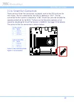
2.2.6.
Smart Fan Connectors
There are two Smart Fan connectors on board: one for the CPU and one for
the chassis. The fan connector for the CPU is labeled as “CN7”. The fan
connector for the system is labeled as “CN8”. Smart Fans provide variable fan
speeds controlled by the BIOS. The fans can be forced to operate at full
speed by disabling the Smart Fan feature in the BIOS. See page 53 for details.
The pinout of the fan connectors is shown below.
CPU fan (CN7)
Pin
Signal
1
FANIN1
2
FANCTL
3
Ground
System fan (CN8)
Pin
Signal
1
FANIN2
2
FANCTL
3
Ground
Table 12: Fan connector pinouts
Figure 17: Fan connectors
Содержание EPIA-M900
Страница 1: ......
Страница 2: ...1 00 06102011 110900 USER MANUAL EPIA M900 Mini ITX embedded board ...
Страница 14: ...EPIA M900 User Manual 6 1 3 Layout Diagram Figure 1 Layout diagram of the EPIA M900 mainboard top view ...
Страница 15: ...EPIA M900 User Manual 7 Figure 2 Layout diagram of the EPIA M900 mainboard bottom view ...
Страница 17: ...EPIA M900 User Manual 9 1 5 Height Distribution Figure 4 Height distribution of the EPIA M900 mainboard ...
Страница 18: ......
Страница 40: ......
Страница 48: ......
Страница 52: ......
Страница 80: ......
Страница 82: ......
Страница 86: ......


