


EPIA-M900 User Manual
16
2.2.
Onboard Connectors
2.2.1.
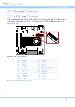
ATX Power Connector
The mainboard has a 20-pin ATX power connector onboard. The ATX power
connector is labeled as “CN6”. The pinout of the ATX power connector is
shown below.
Figure 12: ATX power connector
Pin
Signal
Pin
Signal
1
+3.3V
11
+3.3V
2
+3.3V
12
-12V
3
Ground
13
Ground
4
+5V
14
Power Supply On
5
Ground
15
Ground
6
+5V
16
Ground
7
Ground
17
Ground
8
Power OK
18
-5V
9
+5VSB
19
+5V
10
+12V
20
+5V
Table 7: ATX power connector pinout
Содержание EPIA-M900
Страница 1: ......
Страница 2: ...1 00 06102011 110900 USER MANUAL EPIA M900 Mini ITX embedded board ...
Страница 14: ...EPIA M900 User Manual 6 1 3 Layout Diagram Figure 1 Layout diagram of the EPIA M900 mainboard top view ...
Страница 15: ...EPIA M900 User Manual 7 Figure 2 Layout diagram of the EPIA M900 mainboard bottom view ...
Страница 17: ...EPIA M900 User Manual 9 1 5 Height Distribution Figure 4 Height distribution of the EPIA M900 mainboard ...
Страница 18: ......
Страница 40: ......
Страница 48: ......
Страница 52: ......
Страница 80: ......
Страница 82: ......
Страница 86: ......


