Vetter 1500005102 Скачать руководство пользователя страница 35

Page 35/39

15.2  Compact Gully Sealing Bags

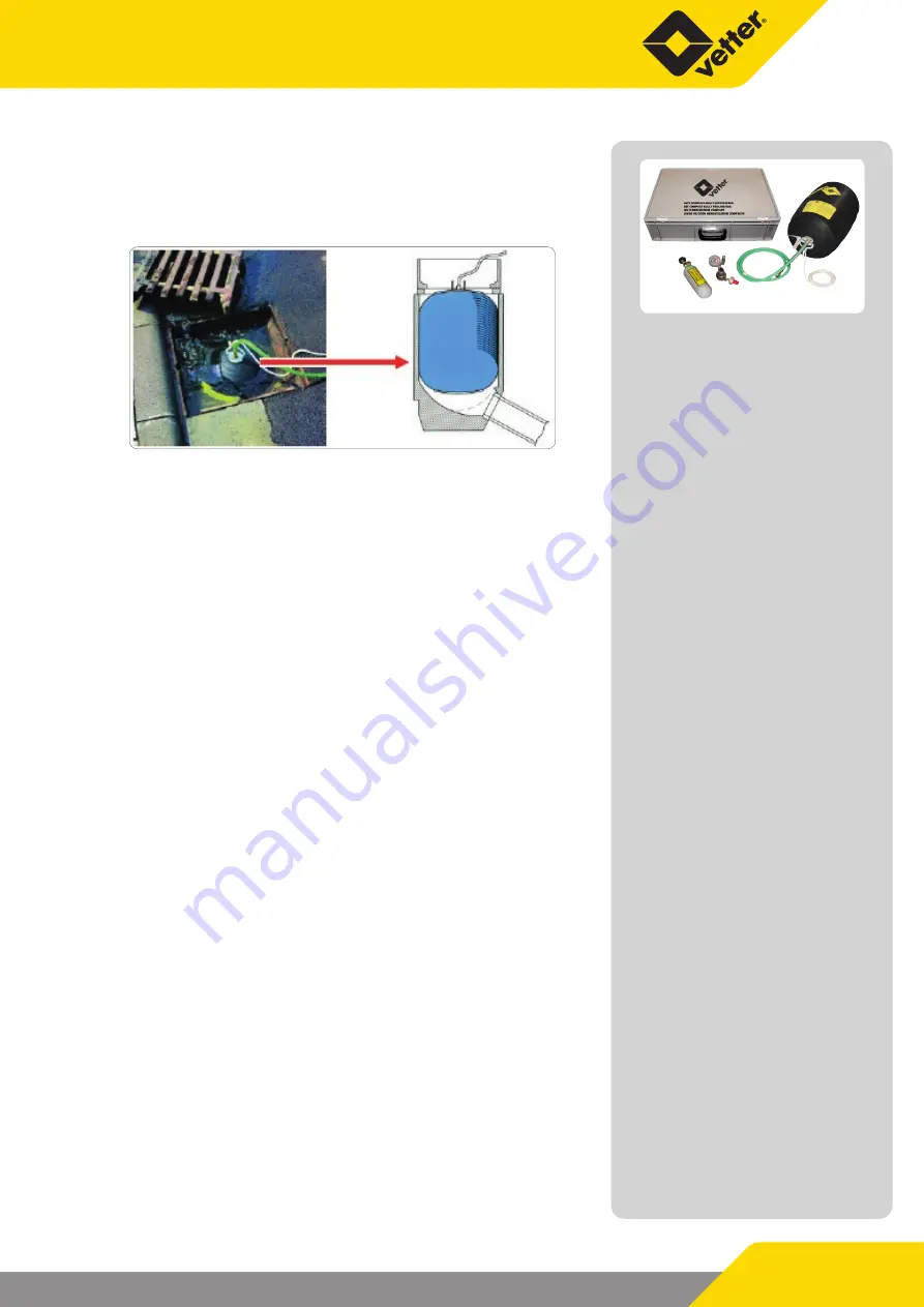
Sewer channel inlets can be quickly sealed with the Vetter Com-
pact Sealing Bag when liquids dangerous for the environment th-
reaten to flow into the sewer network.


9

Firstly remove the cover of the gully and then withdraw the 

dirt collection filter which may be situated underneath.


9

Connect the inflation fitting and safety fitting to the com-

pressed air bottle.


9

Couple the quick connection coupling of the bag inflation 

hose to the nipple of the inflation fitting and safety fitting.


9

Lower the Compact Gully Sealing Bag with inflation hose into 

the open gully using the securing line so that the centre of 

the bag is situated in the round area of the inlet; if necessary, 

firstly inflate the bag slightly until it has a cylindrical shape.


9

Slowly open the compressed air bottle by turning the hand 

wheel.


9

Monitor the maximum operating pressure of the bag on the 

manometer.


9

As soon as the bag is positioned in the round area of the inlet 

and seals (at a maximum of 0.5 bar) close the compressed air 

bottle by turning the hand wheel to the stop.


9

Place the bottle with inflation fitting outside the area of the 

liquid and, if necessary, seal the next gully with another bag.


9

After bag operation, deflate and withdraw it from the gully 

using the securing line.


9

Clean the bag and accessories and inspect for possible dama-

ge. Rub the bag over with talcum powder and roll it up star-

ting from the bottom to the top. Close the safety valve.


9

Determine the pressure reserve remaining in the bottle and, if 

necessary, have the bottle refilled.


9

Connect the refilled bottle again to the inflation fitting and 

safety fitting.


9

Pack the complete connected Compact Gully sealing Bag 

system (bag, inflation hose, inflation fitting and safety fitting, 

compressed air bottle) into the transport case.

Содержание 1500005102

Страница 1: ...Article No 9987033904 Vetter GmbH I 01 19 I Changes and errors excepted Emergency Pneumatics Operating Instructions VETTER Leak Sealers ...

Страница 2: ...ration with foot air pump having safety valve and manometer 9 4 Application of Leak Sealers 10 4 1 Use of the acid protection covering 10 4 2 Preparing for operation 10 4 3 Handling the tension ratchet 12 5 Maintenance and care 13 5 1 Maintenance intervals 13 5 2 Safety valve blow through 14 5 3 Visual test of the safety valve 14 6 Vetter High Pressure Leak Sealing System 15 6 1 Description 15 6 2...

Страница 3: ...plication instructions 25 10 4 After operation 27 10 5 Technical data of Vacuum Leak Draining Bag 28 11 Vetter Leak Sealing Lance 28 11 1 Application instructions 29 11 2 Technical data of the Leak Sealing Lance 30 12 Vetter Leak Sealing Bandages 31 12 1 Technical data 31 13 Vetter Pipe Sealing Sleeves 32 13 1 Technical data Pipe Sealing Sleeves 32 14 Vetter Sealing Paste 33 14 1 Description 33 15...

Страница 4: ...of the product and are to be kept for the complete life duration of the product In case the product should be passed on to a succes sive user then the operating instructions must also be included 1 1 Symbols used This symbol means that there is imminent dan ger If it is not avoided then death or serious in jury will result This symbol means that there is a possible dan gerous situation If it is no...

Страница 5: ...all information contained in these operating instructions 9 9 Compliance to the periods for maintenance and care contai ned in the Chapter Maintenance and Care 2 Safety instructions The use ofVetter Leak Sealers is made under the precondition that there is a knowledge of this application and that the operating instructions are observed 2 1 General information The observance of all pertinent regula...

Страница 6: ... for per fect condition before and after use Damaged seals or seals and accessories which are functionally limited present a source of dan ger and must not be used All controllers are equipped with a safety valve that corresponds to the maximum permitted operation pressure for leak sealers These safety valves will blow when the maximum operating pres sure is exceeded The tolerance for the opening ...

Страница 7: ...s of air Before inflation the leak sealing bags must be correctly and safely tensioned with tension belts on the leak position To do this refer to Chapter 4 3 Handling the tension rat chet Leak sealing bag 9 9 Step 1 Connect the leak sealing bag LD 50 30 S 1 5 bar with guide slots to the inflation hose Inflation hose 9 9 Step 2 Connect the inflation hose to the controller Controller 9 9 Step 3 Con...

Страница 8: ...ressed air connection with blind coupling Close the control line to the blind coupling The tyre inflation connection must be secured with a safety valve as a standard The control line is to be connected with the blind coupling The truck must be secured by brake holding blocks so that it does not roll away Local compressed air network Connection to the outlet coupling of a compressed air network Se...

Страница 9: ... blocking valve The air supply hose with blocking valve can be used as an extensi on between air source and the controller 3 3 Operation with hand pump and foot air pump Hand pump or foot pump for connection to the input coupling of a controller via a 2 m connection hose 3 4 Operation with foot air pump having safety valve and manometer Foot air pump 1 5 bar with safety valve and manometer and 2 m...

Страница 10: ...e in the flap 9 9 The tension belts are accommodated in the upper Velcro fas tener pocket 4 2 Preparing for operation Wear the required protective gear and clothing suitable for the task 9 9 Select and put on the personal protective equipment corres ponding to the degree of danger 9 9 Mark the work area 9 9 Ensure that only authorized persons are in the work area area of danger 9 9 Select the leak...

Страница 11: ...er can damage the pipe or the tank by built up pressures A leak in a container or pipe is a weak point Therefore avoid any additional damage by filling the leak sealer so that no more liquid or gas escapes This can be the case at a point lower than the ma ximum permissible operating pressure Before application of the leak sealer cover sharp edges and or pointed positions in the area of the leak by...

Страница 12: ...tion until the slid is able to lock into the securing groove Opening the ratchet Before opening the ratchet it is imperative to ensure that the leak sealing bag is not under pressure because when opening the rat chet the belt is suddenly released When opening the ratchet the function slid is to be pulled and the ratchet lever is to be swung approximately 180 to the end stop in order to let the sli...

Страница 13: ... Clean the leak sealers with warm water neutral cleaning agent and if necessa ry with a cleaning brush Finally dry at room temperature Acid protection cover Dispose and replace if necessary At least once every year Controller Carry out a visual check and function check Test the function capability of the cou plings nipple manometer and safety valve At least once every year Inflation hose Carry out...

Страница 14: ...er part of the valve again and check for per fect operation 9 9 Changes to the set pressure must not be made 9 9 If the seal on the upper part of the valve is removed then per fect function can no longer be guaranteed The safety valve is then to be sent back to the manufacturer 9 9 With icing caused by high humidity and low temperatures it is possible to use a normal defrosting spray 5 3 Visual te...

Страница 15: ...n If there are inflammable liquid or gas leaks it is im perative that sparks be avoided by fixtures and fittings 6 3 Ground connection 9 9 The inflation valve as well as couplings and joints on the sealing ho ses and on the inflation hose are made of stainless steel 9 9 The sealing hoses are conductive and equipped with a grounding device on both sides 9 9 Fix the ground cable onto the grounding d...

Страница 16: ...on the backpressure mano meter 5 9 9 Connect the ventilation valve 1 to the connection hose 2 of the pressure regulator 9 9 Connect the ventilation valve 1 to the red inflation hose 3 9 9 Close the ventilation valve 9 9 Connect the red inflation hose 3 to the closed inflation valve 4 and couple to the sealing hose 5 9 9 In order to inflate the sealing hose open the outlet valve on the pressure reg...

Страница 17: ...o 1500015901 1500016001 1500016101 Max operating pressure bar 14 14 14 psi 203 203 203 Air requirement at 14 bar Liter 11 1 20 0 27 9 cu ft 0 4 0 7 1 0 Temperature C 30 80 30 80 30 80 F 22 176 22 176 22 176 Approximate weight kg 1 1 1 4 1 8 lbs 2 5 3 3 9 All rights reserved for technical changes within the scope of product improvement ...

Страница 18: ...e until the leak is sealed and that no liquid or gas escapes 7 2 Leak Sealing Bag LD 50 30 S 12 bar with belt guide slots The Vetter Leak Sealing Bag LD 50 30 S 12 bar is used for sealing thick walled containers The tension belts are designed for a ten sile strength of 5000 kg The leak sealing bag LD 50 30 S 12 bar must not be used on plastic containers Plastic containers can be pressed in and dam...

Страница 19: ...ate until the leak is sealed and that no liquid or gas escapes 9 9 Further inflation of the leak sealers can damage the pipe or the container due to pressure build up 7 4 Leak Draining Bag DLD 50 30 With the leak draining bag the leak is sealed and simultaneously the liquid drained away by a drain chamber The sealed area around the drain chamber is blown up so that the liquid can be reliably drain...

Страница 20: ...9 31 7 lbs 64 69 9 LD 50 30 S 12 bar LD 110 60 S XL DLD 50 30 Art No 1500011402 1500014500 1500006001 Size L x W x H cm 61 5 x 30 x 2 110 x 60 x 2 62 x 30 x 6 inch 24 x 12 x 0 8 43 x 24 x 2 7 24 x 12 x 2 4 Sealing area cm 50 x 30 86 x 57 50 x 30 inch 20 x 12 34 x 22 20 x 12 Drain space cm 40 x 20 x 3 5 inch 16 x 8 x 1 4 Max operating pressure bar 12 1 5 1 5 psi 174 21 75 21 75 Test pressure bar 18...

Страница 21: ...pling of the selected mini leak sealing bag 9 9 Prepare the tension belts 9 9 Press the bag centrically onto the leak and place the belt under tension around the container and over the mini leak sealing bag 9 9 Press the Velcro connection over the area 9 9 The tension belts can be connected together to achieve grea ter length and bridge greater container diameters 9 9 When using LDK 10 25 or LDK 2...

Страница 22: ... 7 3 7 x 10 7 7 x 7 7 Max operating pressure bar 1 5 1 5 1 5 psi 21 75 21 75 21 75 Test pressure bar 1 95 1 95 1 95 psi 28 5 28 5 28 5 Sealing pressure m WS 14 14 14 psi 20 3 20 3 20 3 Nominal capacity l 0 3 0 5 2 cu ft 0 01 0 02 0 07 Air requirement at 1 5 bar l 0 8 1 3 5 cu ft 0 03 0 05 0 18 Weight of individual bag approx kg 0 5 0 8 1 1 lbs 1 1 1 8 2 4 in the valve area 6 mm 2 36 inches Weight ...

Страница 23: ...er bag inflation the hazardous material can be drained via the stainless steel ball valve and the acid outlet hose 9 9 Place the collection container to where the hazardous materi al is to be drained 9 9 Lay the flange drainage bag around the leak point and close it with the zip 9 9 Connect the inflation hose of the foot air pump with the con nection coupling on the collar of the flange drainage b...

Страница 24: ...ar 1 5 1 5 1 5 psi 21 75 21 75 21 75 Test pressure bar 1 95 1 95 1 95 psi 28 5 28 5 28 5 Sealing pressure m WS 10 10 10 psi 14 5 14 5 14 5 Nominal capacity l 0 5 0 5 0 5 cu ft 0 02 0 02 0 02 Air requirement at 1 5 bar l 1 25 1 25 1 25 cu ft 0 1 0 1 0 1 Weight of indivi dual bag approx kg 3 1 3 1 3 5 lbs 6 8 6 8 7 7 Weight of kit approx kg 19 0 19 0 19 6 lbs 41 9 41 9 43 2 All rights reserved for t...

Страница 25: ...pecified protective clothing required for operati on 9 9 The sealing of the vacuum leak draining bag is dependent on the condition of the tank wall Therefore under certain condi tions it is necessary to permanently renew the vacuum 9 9 Therefore take care of a suffcient and permanent air supply 9 9 It is therefore necessary to use the Vetter adapter 12 bar Art No 1600015400 for operation with comp...

Страница 26: ...with the outlet hose to the vacuum leak draining bag and open the ball valve 9 9 Prepare the collection container 9 9 Open the blocking valve of the pressure regulator and the va cuum connection until the air can be heard to flow through 9 9 Press the vacuum leak draining bag onto the container wall so that the drainage chamber is centred over the leak position observe the drain chamber size of 20...

Страница 27: ... 6 l 300 bar Input pressure Vacuum Operational time 2 bar 0 15 bar 20 min 3 bar 0 25 bar 14 min 4 bar 0 38 bar 10 min Minimum power of the compressor 200 l min at 4 bar 9 9 Use a Y distributor with additional air supply hose or dual connector when using a number of compressed air bottles 9 9 The vacuum power of the bag can also be increased before operation by wetting the sealing lip with soap or ...

Страница 28: ...ance Kit for leak sealing lance with foot air pump With the Vetter leak sealing lance cracks 15 60 mm long and holes 30 90 mm diameter on storage containers tank trucks and tank wagons can be quickly sealed by one person There are wedge bags and cone bags available for this purpose Air inflation is made with a foot air pump A blocking valve avoids drops in pressure and air losses at the coupling o...

Страница 29: ... hose into the lance coupling until you feel it lock in 9 9 Position the wedge bag or cone bag into the leak 9 9 Using the foot air pump inflate the wedge bag or cone bag un til the leak is sealed maximum operating pressure 1 5 bar 9 9 Close the blocking valve after inflation Safety against over inflation With both inflation versions a safety valve integrated into the foot air pump or in the infla...

Страница 30: ...damage the wedge bag or cone bag must not be used again 11 2 Technical data of the Leak Sealing Lance Wedge bag 6 Wedge bag 8 Wedge bag 11 Cone bag 7 Art No 1500009800 1500010000 1500010100 1500010200 Size L x W x H cm 23 x 6 x 5 23 x 8 x 5 5 23 x 11 x 7 23 x Ø 7 inch 9 x 2 4 x 2 9 x 3 x 2 2 9 x 4 3 x 2 8 9 x Ø 2 8 Maximum ope rating pressure bar 1 5 1 5 1 5 1 5 psi 21 75 21 75 21 75 21 75 Test pr...

Страница 31: ...n nection coupling of the bandage 9 9 Inflate the bandage with the foot air pump until the leak is sealed and no liquid is able to escape 12 1 Technical data LB 5 20 LB 20 48 LB 5 20 XL Art No 1500013900 1500014000 1500018200 Size cm 98 x 21 177 x 21 100 x 40 inch 38 6 x 8 3 69 9 x 8 3 39 4 x 15 7 Sealing area cm 19 wide 19 wide 38 wide inch 7 5 wide 7 5 wide 15 wide Maximum ope rating pressure ba...

Страница 32: ...iameter DN 15 20 25 Size L x W x H mm 133 x 73 x 40 133 x 80 x 50 133 x 90 x 55 inch 5 2 x 2 9 x 1 6 5 2 x 3 1 x 2 5 2 x 3 5 x 2 2 Weight approx kg 1 5 1 7 1 8 lbs 3 3 3 7 4 1 1 4 1 1 2 2 Art No 1500002601 1500002701 1500002801 Nominal size mm 42 4 48 3 60 3 inch 1 7 1 9 2 4 for diameter DN 32 40 50 Size L x W x H mm 133 x 105 x 52 133 x 110 x 52 133 x 125 x 80 inch 5 2 x 4 1 x 2 5 2 x 4 3 x 2 5 2...

Страница 33: ... fluid chemicals and is ideal for temporary immediate measures The seal can be used for several hours up to days It can also be used on slightly rusty greasy or dirty substrates The leak sealing paste is water soluble so it is not suitable for sealing water leaks 9 9 Uniformly press the leak sealing paste firmly into the leak with a spatula starting above the leak Subsequently carefully glue the l...

Страница 34: ...work A guiding rod enables accu rate positioning of the sealing bag The inlet can then be used as a pump sump The Universal Gully Sealing Bag can be used up to a counter pres sure of 10 m water column 9 9 Connect the integrated inflation hose to the foot air pump or controller 2 5 bar 9 9 Position the guiding rod onto the sealing bag 9 9 Position the sealing bag with guiding rod into the outlet an...

Страница 35: ...air bottle by turning the hand wheel 9 9 Monitor the maximum operating pressure of the bag on the manometer 9 9 As soon as the bag is positioned in the round area of the inlet and seals at a maximum of 0 5 bar close the compressed air bottle by turning the hand wheel to the stop 9 9 Place the bottle with inflation fitting outside the area of the liquid and if necessary seal the next gully with ano...

Страница 36: ...7 25 7 25 Test pressure bar 3 25 3 25 0 65 0 65 psi 47 1 47 1 9 4 9 4 Test counter pressure m WS 10 10 2 2 psi 14 5 14 5 2 9 2 9 Cylinder length cm 25 35 41 41 inch 9 8 13 8 16 16 Total length cm 28 5 39 46 46 inch 11 2 15 4 18 1 18 1 Diameter cm 9 14 5 29 5 45 inch 3 5 5 7 11 6 17 7 Nominal content l 3 7 14 3 85 284 cu ft 0 13 0 5 3 10 Air requirement at 0 5 2 5 bar l 13 50 128 426 cu ft 0 5 1 8 ...

Страница 37: ...leak draining bag NR Nylon cord Hot vulcanised High Pressure Leak Sealing System NBR NBR Acid protection cover PVC Polyester Gully leak sealing bag CR Nylon cord Hot vulcanised GFRP articles GFK Fibre glass mats Inflation hoses and air supply hoses EPDM Polyester 16 2 Temperature resistance Products Cold resistance Cold flexible Heat resistance long period Heat resistance short period Hot vulcanis...

Страница 38: ...id o n d o Formaldehyde n d Glucose o Heating oil o Potassium chloride o o Calcium chloride o o Calcium nitrate n d n d n d Carbon dioxide Carbon monoxide n d Copper sulphate o Adhesive n d Methyl chloride n d o o Sea water o n d Mineral oil Sodium carbonate Ozone n d o Paraffin n d o Perchloric acid o n d n d n d o Phenol watery o Phosphoric acid consentrated n d Mercury o n d Nitric acid fuming ...

Страница 39: ... Germany Sales Tel 49 0 22 52 30 08 0 Fax 49 0 22 52 30 08 590 Mail vetter rescue idexcorp com We are the company who can help you find a solution to your problem Place your trust in emergency pneumatics Article No 9987033904 Vetter GmbH I 01 19 I Changes and errors excepted Made in Germany ...

Отзывы: