background image


rev. 3/24/2014 

   LOW, manual.doc 

Copyright 2014 Vestil Manufacturing Corp.                                                                                          6 of 10 

8.  Add spacers and washers to the suspension shafts on both sides of the suspension block. Add spacers and 

washers so that dimension A in FIG. 2 on p. 5 is 

at most

 1/16in. longer than half the flange width (calculated 

in step 7).  

9.  Slide the suspension block onto the suspension shafts. Orient the block with the hand chain of the trolley on 

the opposite side from the hand chain of the trolley. 

10.  Add exactly the same number of spacers and washers on the other side of the suspension block. 
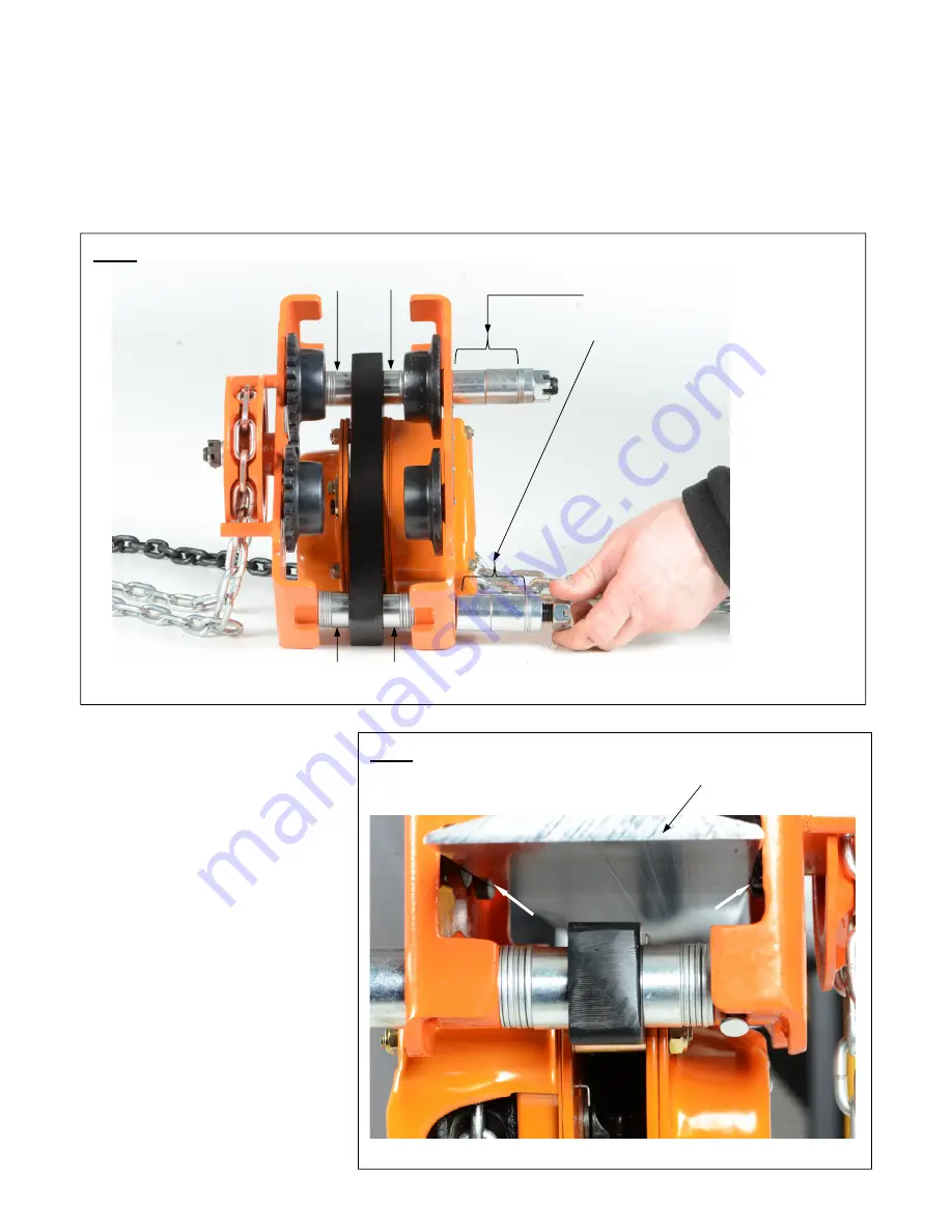
11.  Reinstall the left side plate. 
12.  Slide the spacers and washers that were removed to the ends of the suspension shafts. Maintain symmetry 

when adding spacers and washers, i.e. add the same number and type of spacers/washers to each shaft. 
(See FIG. 4) 


13.  Install the trolley on the lower 

flange of the beam. Track rollers 
ride on the top of the lower 
flange. [NOTE: One end of both 
suspension shafts was left 
unassembled to allow the trolley 
to be installed on the beam 
flange.] 

14.  Reinstall the crown nuts (1) and 

washers (2). Tighten the nuts 
and secure the connections with 
cotter pins (34).  

 
Test the trolley by rolling it several 
feet along the beam flange. If 
necessary, washers and spacers can 
be added symmetrically (on both 
sides of both suspension shafts) to 
allow the trolley to roll more freely. 
However, total clearance between 
the edge of the beam flange and the 
track roller flanges cannot be more 
than 1/8in. (3mm) or 1/16in. per side. 
(Shown by white arrows in FIG. 5). 


Add the same number and type of 
left over spacers and washers to 
each suspension shaft 

Add the same number and type 
of washers and/ or spacers 

Add the same number and type 
of washers and/ or spacers 

FIG. 5:

 Install trolley on beam flange 


FIG. 4:

 Reassembled 

trolley 

Lower beam flange 

Содержание LOW Series

Страница 1: ...ed is exclusively the responsibility of the owner end user 2 Vestil is not liable for any injury or property damage that occurs as a consequence of failing to apply either a the instructions in this m...

Страница 2: ...assisted 4in 8in 513 16 in 103 cm 181 4 in 46 4 cm 6 000 lb 2 727 3kg 150 lb 68 2 kg HAZARD IDENTIFICATION explanation of signal words This manual uses SIGNAL WORDS to indicate the likelihood of perso...

Страница 3: ...ck is in use Slowly raise loads off of the ground Watch the load intently as it is raised The load should not shift or swing as it rises If the load begins to swing or shift in the rigging return the...

Страница 4: ...Wide spacer 4 9 Snap ring 4 10 Bearing cover 4 11 Snap ring 4 12 Deep groove ball bearing 4 13 Geared track roller 2 14 Pinion 1 15 Copper bushing 2 16 Flat washer 1 17 Cotter pin 1 18 Slotted nut 1...

Страница 5: ...e left side plate 3 6 Remove all spacers and washers 5 6 7 8 from both suspension shafts as well as the suspension block 25 NOTE There are 2 kinds of washers 2mm thick washers and 1mm thin washers 7 M...

Страница 6: ...t See FIG 4 13 Install the trolley on the lower flange of the beam Track rollers ride on the top of the lower flange NOTE One end of both suspension shafts was left unassembled to allow the trolley to...

Страница 7: ...tion until all problems discovered during an inspection have been resolved Frequent Inspection At least once per month once per week for heavy service chain blocks and daily for severe service chain b...

Страница 8: ...ntent is subject to change over time and consequently replacement labels might differ from labels shown in the manual supplied with the unit Maintenance Always unload the chain block and trolley befor...

Страница 9: ...chain block a trolley should be labeled as shown in the diagram below Contact Vestil to order a replacement hanging tag if the original tag is lost damaged or unreadable Trolley data tag Chain block d...

Страница 10: ...facility in Angola IN The warranty covers defects in the following original dynamic components motors hydraulic pumps electronic controllers switches and cylinders It also covers defects in original...

Отзывы: