background image

rev. 11/1/2016 

  CB-PMPS, manual.doc 

Copyright 2016 Vestil Manufacturing Corp.                                                                                     Page 23 of 23          


LIMITED WARRANTY  


Vestil Manufacturing Corporation (“Vestil”) warrants this product to be free of defects in material and workmanship 
during the warranty period. 

Our warranty obligation is to provide


a replacement for a defective original part


if


the part is 

covered by the warranty

after we receive a proper request from the warrantee (you) for warranty service


Who may request service? 

Only a warrantee may request service.  

You are a warrantee 

if


you purchased the product from Vestil or from an 

authorized distributor AND Vestil has been fully paid. 


What is an “original part”? 

An original part is a part 

used to make the product as shipped

 to the warrantee. 


What is a “proper request”? 

A request for warranty service is proper if Vestil receives: 1) a photocopy of the Customer Invoice that displays the 
shipping date; AND 2) a written request for warranty service including your name and phone number.  Send requests 
by any of the following methods: 


     Mail   


                  Fax   


Email 

       Vestil Manufacturing Corporation   

           (260) 665-1339   

    [email protected] 

       2999 North Wayne Street, PO Box 507 

                  Phone 

       Angola, IN 46703   


           (260) 665-7586 


In the written request, list the parts believed to be defective and include the address where replacements should be 
delivered. 


What is covered under the warranty?


After Vestil receives your request for warranty service, an authorized representative will contact you to determine 
whether your claim is covered by the warranty.  Before providing warranty service, Vestil may require you to send the 
entire product, or just the defective part or parts, to its facility in Angola, IN. The warranty covers defects in the following 

original

 dynamic components: motors, hydraulic pumps, electronic controllers, switches and cylinders.  It also covers 

defects in 

original

 parts that wear under normal usage conditions (“wearing parts”): bearings, hoses, wheels, seals, 

brushes, batteries, and the battery charger. 


How long is the warranty period?


The warranty period for original components is 1 year. The warranty period begins on the date when Vestil ships the 
product to the warrantee.  If the product was purchased from an authorized distributor, the period begins when the 
distributor ships the product.  Vestil may extend the warranty period for products shipped from authorized distributors 
by 

up to

 30 days to account for shipping time. 


If a defective part is covered by the warranty, what will Vestil do to correct the problem?


Vestil will provide an appropriate replacement for any 

covered

 part.  An authorized representative of Vestil will contact 

you to discuss your claim. 


What is not covered by the warranty? 

1. Labor; 
2. Freight;  
3. Occurrence of any of the following, which automatically voids the warranty: 

 Product misuse; 

  Negligent operation or repair; 

  Corrosion or use in corrosive environments; 

  Inadequate or improper maintenance; 

  Damage sustained during shipping; 

  Collisions or other incidental contacts causing damage to the product; 

 Unauthorized modifications:  DO NOT modify the product IN ANY WAY without first receiving written 

authorization from Vestil.  Modification(s) might make the product unsafe to use or might cause excessive and/or 
abnormal wear. 


Do any other warranties apply to the product? 

Vestil Manufacturing Corp.


makes no other express warranties. All implied warranties are disclaimed to the extent 

allowed by law. Any implied warranty not disclaimed is limited in scope to the terms of this Limited Warranty. 


Содержание CB-PMPS Series

Страница 1: ...om Table of Contents Hazard identification with signal words 2 Safe Use Recommendations 2 Product specifications by model 3 Diagram of Hydraulic System 3 FIG 1 CB PMPS 6 50 exploded parts diagram part...

Страница 2: ...matically void the Limited Warranty see p 23 DO NOT exceed the maximum rated load see Specifications table on p 3 Label 287 on product Inspect the product before each use according to the instructions...

Страница 3: ...0 cm x 91 cm 91 in 231 cm 73 in 187 cm 3 in to 50 in 7 6 cm x 127 cm 2 033 lb 923 8 kg CB PMPS 10 50 1000 lb 455 kg 4 in x 36 in 10 cm x 91 cm 91 in 231 cm 73 in 187 cm 3 in to 50 in 7 6 cm x 127 cm 2...

Страница 4: ...zinc plated bolt 2 5 16 132 227 Caster 8 3 FWB NTP 2 17 37030 1 2in 13 Nylon insert lock nut 2 6 11365 Bolt HHCS 2 zinc plated 3 4 10x3 18 32030 8 18 x 3 4in HWH tek drill tap 2 7 11211 1 2in 13 UNC x...

Страница 5: ...SS zinc plated flat washer 8 5 16 132 173 Caster wheel PH 8 3 2 17 11105 3 8in 16 x 1in HHCS 2 zinc plated bolt 4 6 37039 3 4in 10 zinc plated Nylock nut 2 18 36106 3 8in 16 zinc plated hex nut 4 7 33...

Страница 6: ...16 zinc plated hex nut 4 5 37039 3 8in 10 zinc plated Nylock nut 2 17 16 001 190 FL ADJ 810 adjustable floor lock 1 6 33012 1 2in USS zinc plated flat washer 1 18 15 514 112 Weldment frame 1 7 33625 1...

Страница 7: ...c plated bolt 4 5 37039 3 8in 10 zinc plated Nylock nut 2 17 36106 3 8in 16 zinc plated hex nut 4 6 33012 1 2in USS zinc plated flat washer 1 18 16 001 190 FL ADJ 810 adjustable floor lock 1 7 33625 1...

Страница 8: ...Manufacturing Corp Page 8 of 23 FIG 5 115VAC Modular power unit electrical circuit diagram FIG 6 12VDC Modular power unit electrical circuit diagram Disconnect power before working on the power unit D...

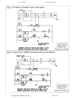
Страница 9: ...ng Corp Page 9 of 23 FIG 7 3 Phase AC Modular Power Unit Diagram Disconnect power before working on the power unit Drawing no 99 124 032 FIG 7 Single Phase 208 230VAC Modular Power Unit Diagram Drawin...

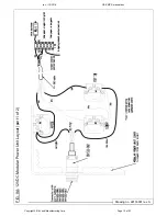
Страница 10: ...rev 11 1 2016 CB PMPS manual doc Copyright 2016 Vestil Manufacturing Corp Page 10 of 23 FIG 9A 12VDC Modular Power Unit Layout part 1 of 2 Drawing no 99133001 rev A...

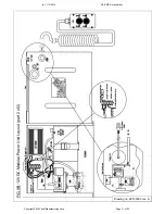
Страница 11: ...rev 11 1 2016 CB PMPS manual doc Copyright 2016 Vestil Manufacturing Corp Page 11 of 23 FIG 9B 12VDC Modular Power Unit Layout part 2 of 2 Drawing no 99133002 rev A...

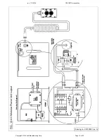
Страница 12: ...rev 11 1 2016 CB PMPS manual doc Copyright 2016 Vestil Manufacturing Corp Page 12 of 23 FIG 10 AC Modular Power Unit Layout Drawing no 99133003 rev A...

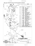
Страница 13: ...rev 11 1 2016 CB PMPS manual doc Copyright 2016 Vestil Manufacturing Corp Page 13 of 23 FIG 11A DC Modular Power Unit Exploded Parts Diagram...

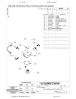
Страница 14: ...rev 11 1 2016 CB PMPS manual doc Copyright 2016 Vestil Manufacturing Corp Page 14 of 23 FIG 11B DC Modular Power Unit Exploded Parts Diagram...

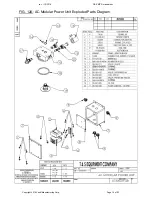
Страница 15: ...rev 11 1 2016 CB PMPS manual doc Copyright 2016 Vestil Manufacturing Corp Page 15 of 23 FIG 12A AC Modular Power Unit Exploded Parts Diagram...

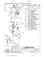
Страница 16: ...rev 11 1 2016 CB PMPS manual doc Copyright 2016 Vestil Manufacturing Corp Page 16 of 23 FIG 12B AC Modular Power Unit Exploded Parts Diagram...

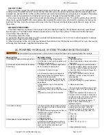
Страница 17: ...To raise the forks press the UP button on the pushbutton controller This starts the electric motor which turns the hydraulic pump and oil from the reservoir then flows through the suction filter and...

Страница 18: ...y voltage Check light b All chassis connections to negative post of battery not made well a Recharge battery b Check and tighten or clean connections if necessary 2 Unit does not raise but motor is ru...

Страница 19: ...owly aa Lowering solenoid valve may be incorrectly wired or is stuck open bb Check valve may be stuck open cc Check for leaking hoses fittings pipes dd Cylinder packings may be worn or damaged aa See...

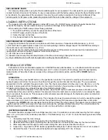
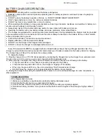
Страница 20: ...harger to a damaged extension cord Every DC powered CB PMPS is equipped with an onboard battery charger having a flanged electrical inlet The charger is current limited and will not exceed its rated o...

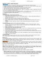
Страница 21: ...damaged hydraulic hoses electrical wires and cords Repair as necessary 5 Carriage rollers see diagrams on p 4 7 check rollers and retaining hardware for normal condition 6 Forks carriage and mast cyc...

Страница 22: ...imited Warranty and might make the pallet handler unsafe to use Step 5 Make a dated record of the repairs adjustments and or replacements Label Placement Diagram Each unit should be labeled at all tim...

Страница 23: ...y in Angola IN The warranty covers defects in the following original dynamic components motors hydraulic pumps electronic controllers switches and cylinders It also covers defects in original parts th...

Отзывы:

Похожие инструкции для CB-PMPS Series