
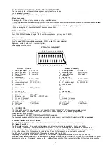
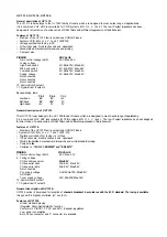
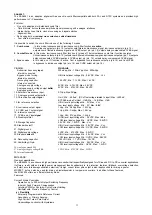

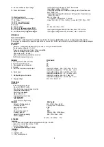


PINNING
1 . Gain control voltage
Tuning voltage
Address select
Serial clock
Serial data
Not connected
Supply voltage
ADC input (optional)
Tuning supply voltage
10. Ground
1 1 . IF output
PIN VALUE
: 4.0V, Max:4.5V
: Max:5.5V
: Min.--0.3V, Max:5.5V
: Min:-0.3V, Max:5.5V
: 5.0V, Min:4.75V, Max:5.5V
: 33V, Min:30V, Max-35V
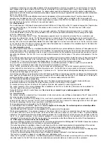
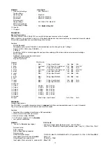
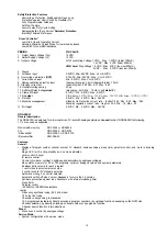
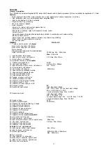
TEA6415C:
General Description:
The main function of the TEA6415C is to switch 8 video input sources on the 6 outputs.
Each output can be switched to only one of the inputs whereas but any same input may be connected to several outputs.
All switching possibilities are controlled through the lyC-bus.
Features:
20 MHz Bandwith
Cascadable with another TEA6415C (Internal address can be changed by pin 7 voltage)
8 inputs (CVBS, RGB, Mac, CHROMA, ...)
6 Outputs
Possibility of MAC or chroma signal for each input by switehing-off the clamp with an external resistor bridge
Bus controlled
6.5dB gain between any input and output
-55dB crosstaljk at 5MHz
Fully ESD protected
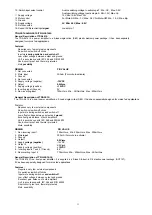
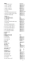
PINNING
PIN VALUE
Max
Low level
Max
Low level
Max
Max
Max
12V
Max
Max
5.5Vpp, Min
5.5Vpp, Min
5.5Vpp, Min
5.5Vpp, Min
5.5Vpp, Min
5.5Vpp, Min
Max: 2Vpp, Input Current : 1mA, Max : 3mA
2Vpp, Input Current
-0.3V Max:1.5V, High level
2Vpp, Input Current
-0.3V Max: 1.5V, High level
2Vpp, Input Current
2Vpp, Input Current
2Vpp, Input Current
2Vpp, Input Current
2Vpp, Input Current
4.5Vpp
4.5Vpp
4.5Vpp
4.5Vpp
4.5Vpp
4.5Vpp
1mA, Max
3.0V Max
1mA, Max
3.0V Max
1mA, Max
1mA, Max
1mA, Max
1mA, Max
1mA, Max
3mA
Vcc+0.5V
3mA
Vcc+0.5V
3mA
3mA
3mA
3mA
3mA
1 . Input
2. Data
3. Input
4. Clock
5. Input
6. Input
7. Prog
8. Input
9. Vcc
10. Input
1 1 . Input
12. Ground
13. Output
14. Output
15. Output
16. Output
17. Output
18. Output
19. Ground
20. Input
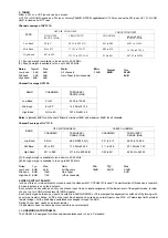
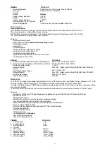
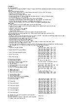
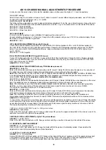
TDA9830:
General description:
The TDA9830, a monolithic integrated circuit, is designed for AM-sound demodulation used in L- and L'-standard.
The 1C provides an audio source selector and also mute switch.
Features:
• Adjustment free wideband synchronous AM demodulator
• Audio source-mute switch (low noise)
• Audio level according EN50049
• 5 to 8V power supply or 12 V alternative
• Low power consumption
PINNING
1 . Sound IF differential input signal
Not connected
AGC capacitor
REF voltage filtering capacitor
Not connected
AM demodulator output
Input signal (from AM) to audio switch
Output signal from audio switch
Input signal (from external) to audio switch
PIN VALUE
; Minimum IF input signal (between pins 1 and 16):60mV
Max:100mV Maximum IF input signal (between pins 1 and 16) :120mV Min :70mV
THD:0.8%, Max:2%; S/N:53dB, Min:47%; DC potential: 2.15V, Min : 2.00V Max :2.30V
Max: 1.2V
80dB, Min : 70dB
Max:1.2V
10
Содержание 11AK19
Страница 1: ...SERVICE MANUAL CHASSIS 11 AK19 FIRMEN EUROLINE PALLADIUM S E G TECHLINE VESTEL...
Страница 27: ...GENERAL BLOCK DIAGRAM OF CHASSIS AK19 26...
Страница 30: ......
Страница 31: ......
Страница 32: ......
Страница 33: ......
Страница 34: ......
Страница 35: ......
Страница 36: ......
Страница 37: ......
Страница 38: ......
Страница 39: ......
Страница 40: ...SERVICE MANUAL VESTEL 11AK19 MODEL...