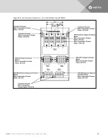
Figure 7.3 Maintenance Bypass Cabinet without transformer
7.4 Removing the Cover Plates
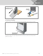
On the back of the Maintenance Bypass Cabinet, cover plates are over the input and output terminals
(see illustration below). Remove these using a phillips screwdriver. Keep screws and plates to one side.
7.5 REPO Connection
Refer to the Installer/User Guide for you Liebert UPS unit for information on connecting the REPO.
7.6 Input and Output Wiring
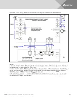
NOTE: Input wiring must be installed using conduit. 208 input voltage jumper—if only the connections
for 208VAC are made between the UPS and the Maintenance Bypass, the 208 input voltage jumper
must be installed for proper operation. To install this jumper, place the jumper wire provided in the
accessory kit between Pin 1 and Pin 2 on TB4.
Vertiv
| Liebert® Maintenance Bypass Cabinet Installer/User Guide |
23
Содержание Liebert Maintenance Bypass Cabinet
Страница 1: ...Liebert Maintenance Bypass Cabinet Installer User Guide ...
Страница 4: ...Vertiv Liebert Maintenance Bypass Cabinet Installer User Guide 4 ...
Страница 8: ...Figure 2 1 Front view Vertiv Liebert Maintenance Bypass Cabinet Installer User Guide 8 ...
Страница 10: ...Figure 2 3 Rear view with transformer Vertiv Liebert Maintenance Bypass Cabinet Installer User Guide 10 ...
Страница 12: ...Vertiv Liebert Maintenance Bypass Cabinet Installer User Guide 12 This page intentionally left blank ...
Страница 14: ...Vertiv Liebert Maintenance Bypass Cabinet Installer User Guide 14 This page intentionally left blank ...
Страница 16: ...Figure 5 1 Clearances Vertiv Liebert Maintenance Bypass Cabinet Installer User Guide 16 ...
Страница 19: ...Vertiv Liebert Maintenance Bypass Cabinet Installer User Guide 19 ...
Страница 20: ...Vertiv Liebert Maintenance Bypass Cabinet Installer User Guide 20 This page intentionally left blank ...
Страница 34: ...Vertiv Liebert Maintenance Bypass Cabinet Installer User Guide 34 This page intentionally left blank ...
Страница 35: ......


