


C h apter 1 O verview 9
L iebert E X S 30 kV A A n d 4 0 kV A U P S U ser M an ual
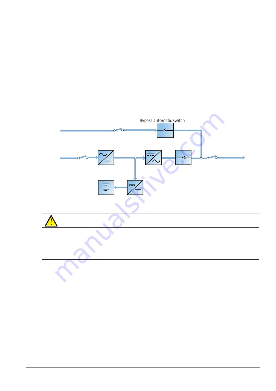
E C O m o d e
If E C O m ode is selected, all pow er sw itches and the battery sw itches are closed except for the m aintenance
bypass sw itch, and the system prefers to put the load on the bypass, to achieve the aim of energy-saving .
W hen the bypass supply is w ithin the rang e of norm al frequency and norm al voltag e (adjustable), the load
is pow ered by the bypass, w ith the inverter on stand-by; w hen the voltage and/or frequency of the bypass
supply are beyond the pre-defined and adjustable lim its, the system w ill transfer to the inverter output, and
the transfer tim e for sw itching from bypass to inverter is less than 4m s. In this m ode, the system can
norm ally charg e the battery.
E C O m ode is an energ y-saving operating m ode. W hen using the U P S to supply equipm ent that is no
sensitive to m ains pow er quality, E C O m ode m ay be used to reduce pow er losses.
Bypass
input
switch
Rectifier
input
switch
Bypass
input
Mains
input
Battery
charger
Output
switch
Inverter
Rectifier
Static
switch
UPS
output
Battery
Inverter
switch
Figure 1-7 Sch em atic diagram of E C O m ode
N o te
1. In E C O m ode, if th e bypass fails or th e bypass voltag e g oes outside n orm al lim its, th e U P S w ill tran sfer to N orm al
m ode (providin g th e outpu t is n ot overloaded). H ow ever, if th e bypass fails o r th e bypass voltag e g oes outside
n orm al lim its w h ile th e outpu t is overloaded, th e U P S w ill n ot tran sfer to N orm al m ode, but w ill sh ut dow n th e B ypass.
2. In E C O m ode, th e efficien cy of th e U P S is in creased to 9 9 % .
3. In E C O m ode, th e load is n ot protected ag ain st m ain s distortion .
P a ra lle l re d u n d a n c y m o d e (s y s te m e x p a n s io n )
For hig her capacity or hig her reliability, the outputs of m ultiple U P S m odules can be program m ed for
directly paralleling w hile a built-in parallel controller in each U P S m odule ensures autom atic load sharing .
T he parallel system can be com posed of up to four U PS m odules. For the operation principle diag ram of the
parallel redundancy m ode, see Figure 6-1.
F re q u e n c y c o n v e rte r m o d e
T he U P S can be prog ram m ed into frequency converter m ode for either 50 H z or 60 H z stable output
frequency. T he input frequency m ay vary from 40 H z to 70 H z . U nder this m ode, it is required to open the
m aintenance bypass sw itch to disable the bypass operation, and the battery becom e s optional depending
on any requirem ent to operate in battery m ode.
Содержание EXS 0030kTH 16FN01000
Страница 1: ...Liebert EXS 30kVA And 40kVA UPSUPS User Manual...
Страница 2: ......
Страница 61: ......


