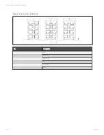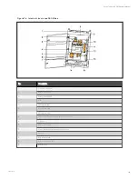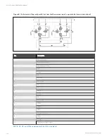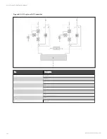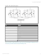
F igu re 7.4 In tern al stru ctu re o f B CB bo x
N o.
D es crip tion
1
Top cable entry hole
2
Battery terminal (+)
3
Battery terminal (N)
4
BCB
5
UPS terminal (+)
6
UPS terminals (N)
7
UPS terminals (-)
8
Current transformer of battery ground fault detector
9
Top plate
10
Battery terminal (-)
11
Control board of battery ground fault detector
12
Earth bar
13
BCB control board
14
Bottom cable entry hole
15
Bottom plate
7 Battery
129
Vertiv™ Liebert® APM Plus User Manual
Содержание APM 0250kMK16FN02000
Страница 1: ...Vertiv Liebert APM Plus User Manual 50 250 kVA UPS...
Страница 8: ...vi This page intentionally left blank Vertiv Liebert APM Plus User Manual...
Страница 16: ...1 Important Safety Instructions 8 This page intentionally left blank Vertiv Liebert APM Plus User Manual...
Страница 30: ...2 Overview 22 This page intentionally left blank Vertiv Liebert APM Plus User Manual...
Страница 60: ...4 Electrical Installation 52 This page intentionally left blank Vertiv Liebert APM Plus User Manual...
Страница 73: ...Figure 5 11 Customize the display 5 Operator Control and Display Panel 65 Vertiv Liebert APM Plus User Manual...
Страница 97: ...5 Operator Control and Display Panel 89 Vertiv Liebert APM Plus User Manual...
Страница 154: ...Figure 8 8 LBS port J4 on bypass control module 8 Parallel System and LBS System 146 Vertiv Liebert APM Plus User Manual...
Страница 182: ...11 Service and Maintenance 174 This page intentionally left blank Vertiv Liebert APM Plus User Manual...
Страница 188: ...12 Specifications 180 This page intentionally left blank Vertiv Liebert APM Plus User Manual...
Страница 191: ...Vertiv Liebert APM Plus User Manual...

