


5-5
U
With the transceiver set to the band center fre-
quency channel (CH2), and with the RF signal
generator tuned to the same frequency, set the
generator for ±3.0 kHz deviation with 1 kHz tone
modulation, and set the output level for –6.0 dB
μ
at the antenna jack.
U
Adjust
T1001
,
T1001
,
T1001
and T1004 the re-
ceiver front-end tuning for optimum SINAD, re-
ducing signal generator output level as necessary
for proper meter deflection.
U
After the previous step, the final signal generator
level should be less than –6 dB
μ
for 12dB SINAD.
U
With the transceiver set to the band high fre-
quency channel (CH3), and with the RF signal
generator tuned to the same frequency, set the
generator for ±3.0 kHz deviation with 1 kHz tone
modulation, and set the output level for –6.0 dB
μ
at the antenna jack.
U
After the previous step, and confirm the final sig-
nal generator level should be less than –6 dB
μ
for
12dB SINAD.
U
With the transceiver set to the band low frequency
channel (CH1), and with the RF signal generator
tuned to the same frequency, set the generator for
±3.0 kHz deviation with 1 kHz tone modulation,
and set the output level for –5.0 dB
μ
at the an-
tenna jack.
U
After the previous step, and confirm the final sig-
nal generator level should be less than –5 dB
μ
for
12dB SINAD.
Squelch Threshold
The squelch parameters can also be adjusted from
the computer by utilizing the Alignment Software.
Refer to the onboard help of the Alignment Software
Manual for details.
Tight SQL RSSI LEVEL
U
Select the band center frequency channel (CH2),
and with the RF signal generator turned to the
same frequency, set the generator for ±3.0 kHz de-
viation with 1 kHz tone modulation, and set the
output level for 12.0 dB
μ
at the antenna jack.
Threshold NSQ LEVEL
U
Select the band center frequency channel (CH2),
and with the RF signal generator turned to the
same frequency, set the generator for ±3.0 kHz de-
viation with 1 kHz tone modulation, and set the
output level for –6.0 dB
μ
at the antenna jack.
Tight SQL NSQ LEVEL
U
Select the band center frequency channel (CH2),
and with the RF signal generator turned to the
same frequency, set the generator for ±3.0 kHz de-
viation with 1 kHz tone modulation, and set the
output level for 6.0 dB
μ
at the antenna jack.
Содержание VX-6000L
Страница 13: ...1 12 Operating Manual Reprint Note ...
Страница 17: ...3 2 Block Diagram ...
Страница 18: ...3 3 Block Diagram ...
Страница 19: ...3 4 Interconnection Diagram ...
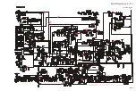
Страница 31: ...6A 5 MAIN Unit Lot 18 Circuit Diagram ...
Страница 32: ...6A 6 MAIN Unit Lot 18 Circuit Diagram ...
Страница 52: ...6A 26 MAIN Unit Note ...
Страница 53: ...6B 1 DISPLAY Unit Circuit Diagram ...
Страница 54: ...6B 2 DISPLAY Unit Note ...
Страница 55: ...6B 3 DISPLAY Unit Parts Layout Side A 1 2 3 F A C B E D ...
Страница 56: ...6B 4 DISPLAY Unit g 1 2 3 e b a d c f Parts Layout Side B ...
Страница 62: ...6B 10 DISPLAY Unit Note ...
Страница 64: ...6C 2 KEY Unit Note ...
Страница 66: ...6C 4 KEY Unit Note ...
Страница 70: ...Note ...
Страница 73: ...6E 3 Circuit Diagram PA Unit Lot 18 ...
Страница 78: ...6E 8 PA Unit Note ...
Страница 94: ...7E 4 Note FIF 7 Connection Unit ...


