EVX-531 UHF Service Manual
16
5. tx p
ower
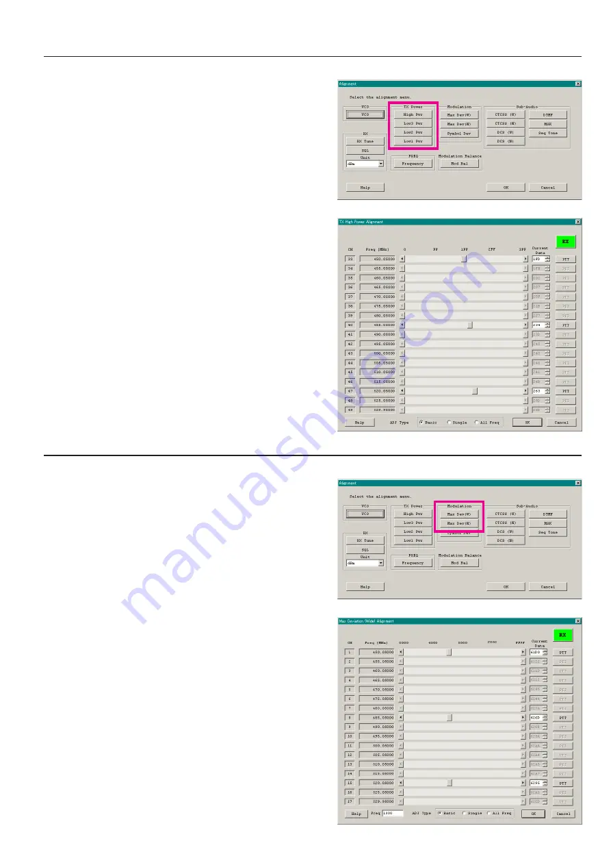
This parameter is to align the “High Power”, “Low3 Power”, “Low2 Power”, or “Low1 Power” for the selected channel.
1. Click the “TX Power (High Pwr / Low3 Pwr / Low2 Pwr /
Low1 Pwr)” button to open the “TX Power Alignment” win-
dow.
2. Click the “PTT” button on the desired channel. The radio starts
to transmit on the selected channel.
3. Set the value to get desired output power (High: 5 W, Low3: 2.5
W, Low2: 1 W, Low1: 250 mW) on the Power Meter according
to the following ways:
l
Dragging the slide bar
l
Clicking the arrow buttons
l
Pressing the left/right arrow key of the computer’s keyboard
l
Entering the value in the entry box from the computer’s
keyboard
4. After getting the desired output power, click the “PTT” button
or press the “SPACE” bar to stop transmitting.
5. Click the “OK” button to finish the TX Power alignment and
save the data.
You may select the adjusting type from the “Radio” button (
ADJ
Type
) located at the bottom of the screen, as needed.
Basic
:
“Low-edge / band center / high-edge” and select the
channel for alignment (Default).
Single
: Alignment value changes only on the selected chan-
nel.
All Freq
: Alignment value changes on all channels.
Alignment
6. m
aximum
d
eviation
<w
ide
> / <n
arrow
>
This parameter is to align the “Maximum Deviation” (Wide/Narrow).
1. Press the “Max Dev (W/N)” button to open the “Max Deviation
Alignment” window.
2. Click the “PTT” button on the desired channel. The radio starts
to transmit on the selected channel.
3. Set the value to get desired deviation (Wide: 4.2 kHz, Narrow:
2.1 kHz) on the deviation meter according to the following
ways:
l
Dragging the slide bar
l
Clicking the arrow buttons
l
Pressing the up-down key of the computer’s keyboard
l
Entering the value in the entry box from the computer’s
keyboard
4. After getting the desired deviation, click the “PTT” button or
press the “SPACE” bar to stop transmitting.
5. Click the “OK” button to finish the Max Deviation alignment
and save the data.
1) You may align the deviation level by any modulation frequency
by changing the value of the “Freq” box located at the bottom
left of the screen, if needed.
2) You may select the alignment type from the “Radio” button
(
ADJ Type
) located at the bottom of the screen, as needed.
Basic
:
“Low-edge / band center / high-edge” and select the
channel for alignment (Default).
Single
: Alignment value changes only on the selected chan-
nel.
All Freq
: Alignment value changes on all channels.
ê
ê
Содержание EVX-531
Страница 8: ...EVX 531 UHF Service Manual Block Diagram 8 ...
Страница 24: ...EVX 531 UHF Service Manual 24 MAIN Unit Type G7 w o Option Connector Circuit Diagram FR024460D RF Sections ...
Страница 27: ...EVX 531 UHF Service Manual 27 MAIN 2 Unit Type G6 w o Option Connector Circuit Diagram FR025510A RF Sections ...


