4-10
39014-03 06/16
VERSALIFT VST-36/40/47/52-I
OPERA
TION
The optional lifting eye has been designed to
accommodate limited material handling. Always
extend the outriggers (if so equipped) and fully retract
the inner boom when using the boom lifting eye. Boom
movements should be smooth to avoid swinging the
load. Do not exceed the load limits stated on the
decal beside the lifting eye. Do not drag the load with
the lifting eye. This is a bad practice and subjects
the unit to damaging sideloads. When lifting loads,
position the lower boom directly over the load before
lifting. The platform should be empty when lifting loads.
When the truck is not level, extreme caution must be
used when rotating loads toward the low side because
the truck stability will be affected.
The platform must
not be used for material handling.
The platform
was designed to lift personnel only.
DANGER:
INCREASING THE
HORIZONTAL DISTANCE FROM THE TRUCK TO
THE LOAD WILL REDUCE THE STABILITY OF THE
TRUCK AND MAY RESULT IN DEATH OR
SERIOUS INJURY.
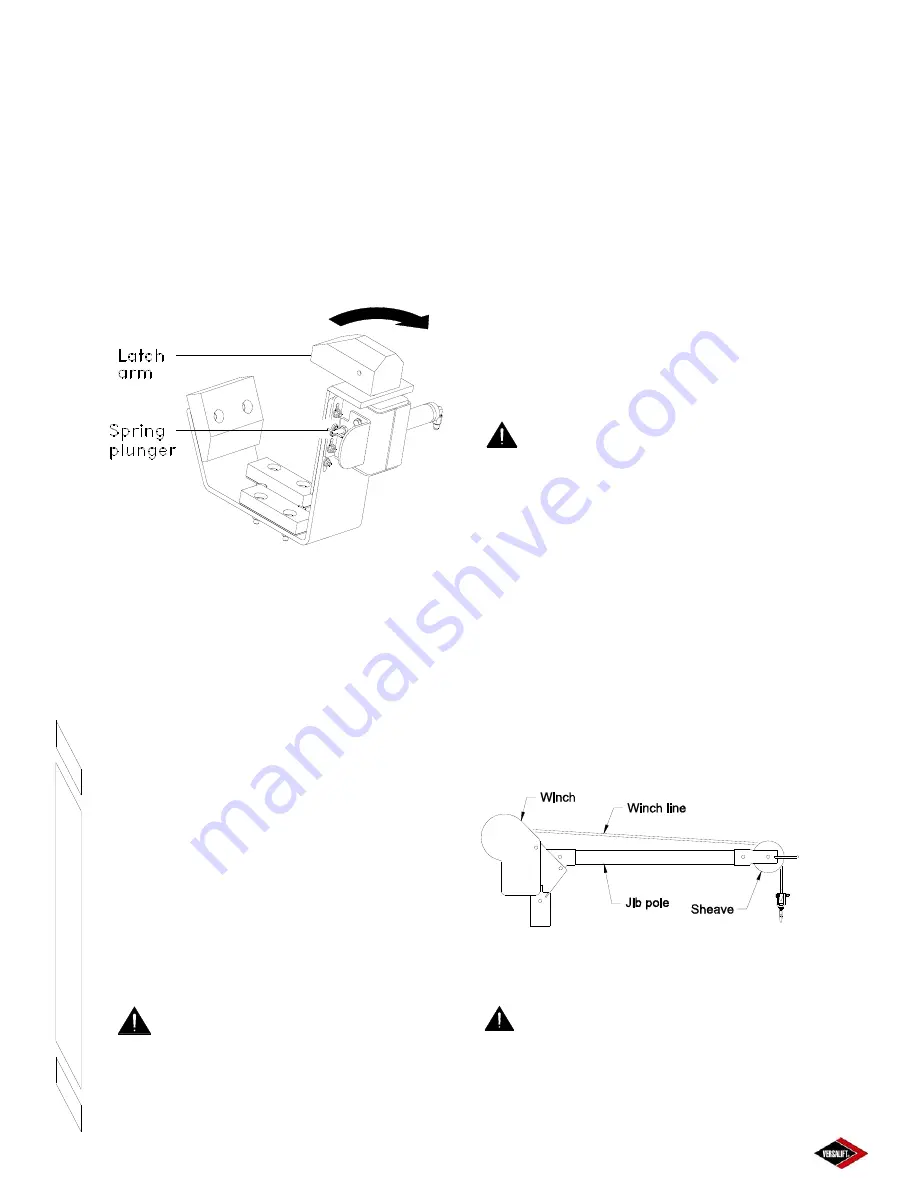
MANUAL JIB OPERATION
The optional material handling system is designed to
lift loads to the work site at the platform. The main
components of this system are the sheave, winch
line, jib pole, and the winch. The jib pole tilts and
rotates manually. Although some of the components
of the jib and winch are made from non-conductive
materials, they are not tested or maintained as
insulating. Therefore, the entire jib and winch
assembly, including the jib pole and rope, must be
considered conductive and have no insulating value.
Manual Jib Major Components
Figure 4.9
DANGER:
DEATH OR SERIOUS
INJURY MAY RESULT FROM MISUSE OR
FAILURE CAUSED BY MISUSE OF THE AERIAL
LIFT OR ITS COMPONENTS. BEFORE
OPERATION, KNOW THE INSTRUCTIONS AND
LIMITATIONS OF THE LIFT AND THE MATERIAL
HANDLING SYSTEM.
Over-ride Procedure:
1.
Danger
– Make sure the hydraulic power source
is off.
2.
Release the spring plunger by rotating the “T”
handle.
3.
Manually rotate the latch arm 90° clockwise until
it snaps and is held by the spring plunger.
To Release Over-ride:
1.
Caution
– The latch is spring loaded. Keep
fingers clear to prevent pinching.
2.
Slightly rotate the latch arm clockwise to remove
the load from the spring plunger.
3.
While holding the latch arm, pull the spring
plunger out and rotate the “T” handle to lock the
spring plunger in the “out” position.
4.
Carefully allow the latch arm to rotate counter-
clockwise under spring power until it stops.
LIFTING EYE (OPTION)
This aerial lift is designed primarily as a personnel lift.
When tools or equipment are included with the operator
in the platform the combined weight must not exceed
the rated load capacity of the aerial lift.
DANGER:
NEVER EXCEED THE
RATED LOAD CAPACITY OF THE AERIAL LIFT.
STRUCTURAL DAMAGE OR INSTABILITY MAY
RESULT, CAUSING DEATH OR SERIOUS INJURY.
Содержание VST-36-I
Страница 2: ......
Страница 4: ......
Страница 6: ......
Страница 11: ...2 3 39014 03 06 16 VERSALIFT VST 36 40 47 52 I RESPONSIBILITIES SAFETY ...
Страница 12: ...2 4 RESPONSIBILITIES SAFETY 39014 03 06 16 VERSALIFT VST 36 40 47 52 I ...
Страница 18: ......
Страница 27: ...3 9 39014 03 06 16 VERSALIFT VST 36 40 47 52 I SPECIFICATIONS ...
Страница 28: ...3 10 39014 03 06 16 VERSALIFT VST 36 40 47 52 I SPECIFICATIONS ...
Страница 29: ...3 11 39014 03 06 16 VERSALIFT VST 36 40 47 52 I SPECIFICATIONS ...
Страница 30: ...3 12 39014 03 06 16 VERSALIFT VST 36 40 47 52 I SPECIFICATIONS ...
Страница 31: ...3 13 39014 03 06 16 VERSALIFT VST 36 40 47 52 I SPECIFICATIONS ...
Страница 36: ...3 18 39014 03 06 16 VERSALIFT VST 36 40 47 52 I SPECIFICATIONS ...
Страница 37: ...3 19 39014 03 06 16 VERSALIFT VST 36 40 47 52 I SPECIFICATIONS ...
Страница 38: ......
Страница 60: ...6 4 39014 03 06 16 VERSALIFT VST 36 40 47 52 I DAILY VISUAL INSPECTION ...
Страница 61: ...6 5 39014 03 06 16 VERSALIFT VST 36 40 47 52 I DAILY VISUAL INSPECTION ...
Страница 62: ...6 6 39014 03 06 16 VERSALIFT VST 36 40 47 52 I DAILY VISUAL INSPECTION ...


