


4-9
39014-03 06/16
VERSALIFT VST-36/40/47/52-I
OPERA
TION
DANGER
:
ALWAYS WATCH FOR
PERSONNEL AND OBSTRUCTIONS WHEN
STORING THE AERIAL LIFT. A CRUSHING INJURY
TO PERSONNEL OR DAMAGE TO THE UNIT CAN
OCCUR.
To complete the storing procedure secure the upper
boom with the tie down strap, retract the outriggers,
and remove the wheel chocks. Turn the electrical
control system off and disengage the PTO pump drive.
CAUTION
:
TO PREVENT DAMAGE
TO THE UNIT DO NOT DRIVE THE TRUCK UNTIL
THE AERIAL LIFT IS STORED AND THE OUTER
BOOM IS SECURED WITH THE BOOM TIE
DOWN STRAP.
CAUTION:
DRIVING WITH THE PTO
ENGAGED MAY DAMAGE THE TRANSMISSION,
PUMP, AND THE PTO.
AUTO BOOM LATCH (optional)
– The automatic
boom latch is designed to open automatically when
the lift is operated. Stay clear of the latch as it may
move at any time depending on the hydraulic system
pressure.
Manual over-ride
– In case of hydraulic system
failure, the auto boom latch may be operated
manually.
BACKUP PUMP CONTROL (Option)
- The backup
pump system is operated by an air cylinder plunger
knob.
The backup pump system should not be
operated longer than 30 seconds continuously.
Continuous use will drain the battery and damage
(over heat) the backup pump motor.
To activate this system from the upper controls,
push the air cylinder plunger knob down and hold it
while operating the lift controls.
To turn off the backup pump from the upper
controls,
release the air cylinder knob and allow it
to return to the neutral position.
STORING THE AERIAL LIFT
When storing the aerial lift for road travel retract the
inner boom completely. Rotate the outer/inner boom
assembly until it is centered over the boom rest.
Rotate the platform so the bottom of the platform is
centered over the platform support. Always stow the
lower boom before descending the outer/inner boom
assembly onto the boom rest. Release the outer/
inner boom control lever as soon as there is firm
contact with the boom rest pad. The platform will
also contact the spring-loaded platform support.
CAUTION
:
FAILURE TO STOW THE
LOWER BOOM BEFORE DESCENDING THE
OUTER/INNER BOOM ASSEMBLY ON TO THE
BOOM REST WILL STRESS THE COMPONENTS
AND MAY CAUSE DAMAGE TO THE AERIAL
LIFT.
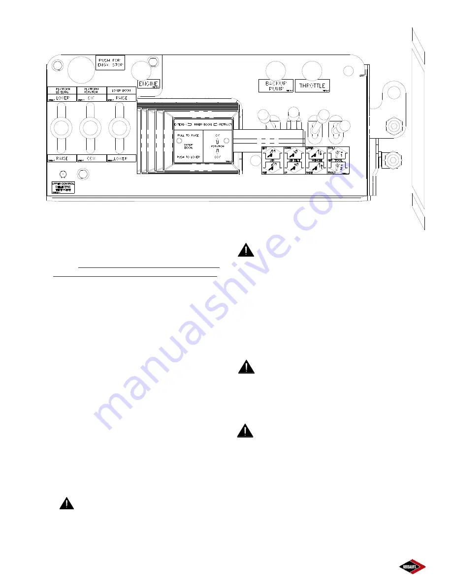
3-Axis Upper Controls w/ Truguard
(For Reference Only - Options May Vary)
Figure 4.8
Содержание VST-36-I
Страница 2: ......
Страница 4: ......
Страница 6: ......
Страница 11: ...2 3 39014 03 06 16 VERSALIFT VST 36 40 47 52 I RESPONSIBILITIES SAFETY ...
Страница 12: ...2 4 RESPONSIBILITIES SAFETY 39014 03 06 16 VERSALIFT VST 36 40 47 52 I ...
Страница 18: ......
Страница 27: ...3 9 39014 03 06 16 VERSALIFT VST 36 40 47 52 I SPECIFICATIONS ...
Страница 28: ...3 10 39014 03 06 16 VERSALIFT VST 36 40 47 52 I SPECIFICATIONS ...
Страница 29: ...3 11 39014 03 06 16 VERSALIFT VST 36 40 47 52 I SPECIFICATIONS ...
Страница 30: ...3 12 39014 03 06 16 VERSALIFT VST 36 40 47 52 I SPECIFICATIONS ...
Страница 31: ...3 13 39014 03 06 16 VERSALIFT VST 36 40 47 52 I SPECIFICATIONS ...
Страница 36: ...3 18 39014 03 06 16 VERSALIFT VST 36 40 47 52 I SPECIFICATIONS ...
Страница 37: ...3 19 39014 03 06 16 VERSALIFT VST 36 40 47 52 I SPECIFICATIONS ...
Страница 38: ......
Страница 60: ...6 4 39014 03 06 16 VERSALIFT VST 36 40 47 52 I DAILY VISUAL INSPECTION ...
Страница 61: ...6 5 39014 03 06 16 VERSALIFT VST 36 40 47 52 I DAILY VISUAL INSPECTION ...
Страница 62: ...6 6 39014 03 06 16 VERSALIFT VST 36 40 47 52 I DAILY VISUAL INSPECTION ...


