background image

VERMONT CASTINGS, INC. 

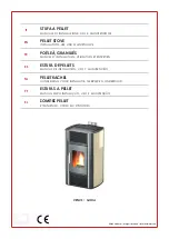
Intrepid II

Model No. V10R NAT. GAS

V10G

  V10CB

  Model No. V12R L.P.G

V12G

  V12CB

GC No. 32-227-01


DECORATIVE COAL EFFECT GAS STOVE

Installation and Maintenance Instructions

Hand these instructions to the user 
This appliance is only for use on Natural Gas (G20) at a supply
pressure of 20 mbar in GB / IE (Model No. V10)
or

Содержание Intrepid II

Страница 1: ...B Model No V12R L P G V12G V12CB GC No 32 227 01 DECORATIVE COAL EFFECT GAS STOVE Installation and Maintenance Instructions Hand these instructions to the user This appliance is only for use on Natural Gas G20 at a supply pressure of 20 mbar in GB IE Model No V10 or ...

Страница 2: ...2 Propane G31 at a supply pressure of 37mbar in GB IE Model No V12 ...

Страница 3: ...nstallation into brick or stone built 11 13 chimney 2 6 Installation into brick or stone built chimney 14 16 utilising a closure plate 2 7 Installation using metal flue pipe with no 17 19 chimney 2 9 Rotation of the flue spigot collar 20 21 2 10 Fitting the flue pipe or elbow to the stove 21 2 11 Making the gas connection 22 2 12 Gas soundness burner pressure 22 Section 3 Assembling Fuel Bed and C...

Страница 4: ... 1 0mbar Nat gas 8 0 0 4 in w g 37 1 0mbar LPG 14 8 0 4 inw g Ignition Integrated piezo ignition on Valve Electrode Spark Gap 4 5mm Weight not including packaging 79 Kg Stove Dimensions Width 545mm Height Top vent 642mm Height Back vent 610mm Depth Top vent 540mm Flue collar size 150mm diameter Gas Connection 8mm Compression Supplied with stove 32mm to end of horizontal vent collar 540mm 350mm 180...

Страница 5: ...pplicable requirements of the following British Standard Code of Practice 1 B S 5871 Part 3 Installation of Decorative Fuel Effect Gas Fires 2 B S 6891 Installation of Gas Pipework 3 B S 5440 Parts 1 2 Installation of Flues and Ventilation 4 B S 715 Metal flue pipes for gas appliances 5 B S 6461 Part 1 Installation of Chimneys and flues 6 B S 1289 Clay Flue Blocks and Terminals 7 I S 813 1996 Dome...

Страница 6: ...ARANCES TO COMBUSTIBLE BEAMS WITHIN INGLENOOKS TOP FLUE FITTING The stove may be below a combustible beam providing there is a minimum distance of 610mm above the top of the stove and that it does not extend in front of the stove There must be a minimum distance of 300mm to any combustible side or rear surface and 100mm to any non combustible side or rear surface 1 5 FLUE CHIMNEY INSPECTION Forwar...

Страница 7: ...after the smoke pellet test 5 The stove can be installed into various flue pipes in accordance with BS 715 with a minimum internal diameter of 125mm 6 Using a smoke pellet check that there is an up draught in the chimney flue and that the smoke can be seen issuing from the terminal chimney pot outside There must be no leakage of smoke through the structure of the chimney during or after the smoke ...

Страница 8: ...tem is exchanged only a complete original manufacturers part may be fitted It is not possible to replace individual parts on this appliance only a complete assembly may be fitted 1 8 FITTING THE REMOVEABLE HANDLE TO THE STOVE DOOR The door handle which comes with the stove is designed to be removeable to prevent overheating during long periods of use To use the handle simply slide the collar into ...

Страница 9: ...e factory we coat the griddle with vegetable oil to prevent rusting while the stove is in transit or storage Remove the oil with a dry rag or paper towel before you use the stove 2 2 INSTALLING THE STOVE Due to the weight of this appliance 79kg it does not require any additional fixing methods There are several methods of installing the flue system for use with the Intrepid II stove Please follow ...

Страница 10: ...dimensions when measured on individual installations must not calculate to exceed a void volume of 247dm3 or be less than 12 dm3 See page 14 for example calculation Flat Surface Area Width 525mm Height 660mm Height Min 635mm Max 660mm Width Min 450mm Max 500mm Depth Min 200mm Max See Note Below ...

Страница 11: ...into Non Combustible Surround Minimum D Dimension 560mm into Non Combustible Surround Minimum E Dimension 760mm into Combustible Surround NOTE Maximum dimensions are not specified due to limiting installation possibilities Height Min C 742mm For Max Dimensions See Note Below Width Min A 745mm Min B 1145mm For Max Dimensions See Note Below Depth Min D 560mm Min E 760mm For Max Dimensions See Note B...

Страница 12: ...late and to the base of the chimney where the flue pipe enters the chimney This should be sealed using a suitable fire cement or proprietary sealing compound If you are fitting the flue pipe directly horizontal on the stove you will need to reverse the outlet spigot on the stove as it is factory set in the vertical position See page 20 21 for details of how to reverse this spigot back to the horiz...

Страница 13: ...UE PIPES TO BE SEALED TO DEBRIS REGISTER PLATE AND TO THE ENTRANCE TO THE CHIMNEY WITH SUITABLE TAPE FLUE OF MINIMUM 5 125MM DIAMETER MINIMUM EFFECTIVE FLUE HEIGHT 2 5 METRES FLUE SYSTEM TO TERMINATE WITH A CHIMNEY POT OR FLUE TERMINAL COMPLYING WITH BS 5440 PART 1 MINIMUM CLEARANCE 50MM MINIMUM 100mm ...

Страница 14: ...HIMNEY FLUE PIPES TO BE SEALED TO DEBRIS REGISTER PLATE AND TO THE ENTRANCE TO THE CHIMNEY WITH SUITABLE TAPE FLUE OF MINIMUM 5 125MM DIAMETER MINIMUM EFFECTIVE FLUE HEIGHT 2 5 METRES 150MM FLUE SYSTEM TO TERMINATE WITH A CHIMNEY POT OR FLUE TERMINAL COMPLYING WITH BS 5440 PART 1 MINIMUM CLEARANCE 50MM MINIMUM 100mm ...

Страница 15: ...he flue pipe enters the chimney This should be sealed using a suitable fire cement or proprietary sealing compound The flue spigot outlet has been fitted to the appliance from the factory in the vertical position You must ensure that the void volume behind the catchment area is a minimum of 12 dm3 The void including that which may be created by any ledge should not be so large as to adversely affe...

Страница 16: ...closure plate supplied With the debris register plate sealed into position and any sealing compound cured and with the flue outlet spigot in the correct position set the stove to its required position and insert and seal the flue pipe into the closure plate Once this is complete proceed with the connection of the gas supply fuelbed layout and commissioning of the stove See page 31 for flue pipe el...

Страница 17: ...T 2 5 METRES INTEGRAL CHIMNEY LINER MINIMUM 125MM 5 DIAMETER FLUE SYSTEM TO TERMINATE WITH A CHIMNEY POT OR A FLUE TERMINAL COMPLYING WITH BS 5440 PART 1 DEBRIS REGISTER PLATE TO BE SEALED TO THE CHIMNEY WITH SUITABLE TAPE CLOSURE PLATE TO BE SEALED TO WALL WITH TAPE ETC WITH AN ADHESIVE STRENGTH OF 100 DEG C VOID VOLUME TO BE A MINIMUM OF 12 dm3 MAXIMUM VOLUME AS PER INFORMATION ON PAGE 17 MINIMU...

Страница 18: ...m to the requirements of BS 715 A minimum effective flue height of 2 5m from the centre of the flue outlet spigot is required and a flue terminal conforming to the requirements of BS 5440 Part 1 will need to be fitted The flue spigot outlet has been fitted to the appliance from the factory in the vertical position if you require to fit the flue pipe in the horizontal position you must rotate the f...

Страница 19: ...EY POT OR A FLUE TERMINAL COMPLYING WITH BS 5440 PART 1 FLUE PIPE OF MINIMUM 5 125mm DIAMETER OR EQUIVALENT CROSS SECTIONAL AREA COMPLYING WITH BS 715 MINIMUM EFFECTIVE FLUE HEIGHT 2 5 METRES MAXIMUM 150MM HORIZONTAL FLUE LENGTH ENSURE THAT CLEARANCES NORMALLY 50MM FOR COMBUSTIBLE MATERIALS COMPLY WITH YOUR LOCAL AND NATIONAL BUILDING REGULATIONS MINIMUM 50mm CLEARANCE ...

Страница 20: ...M DIAMETER OR EQUIVALENT CROSS SECTIONAL AREA COMPLYING WITH BS 715 FLUE SYSTEM TO TERMINATE WITH A CHIMNEY POT OR A FLUE TERMINAL COMPLYING WITH BS 5440 PART 1 MINIMUM EFFECTIVE FLUE HEIGHT 2 5 METRES ENSURE THAT CLEARANCES NORMALLY 50MM TO COMBUSTIBLE MATERIALS COMPLY WITH LOCAL AND NATIONAL BUILDING REGULATIONS MINIMUM 50MM CLEARANCE ...

Страница 21: ...cal position from which it is set at the factory to the horizontal position To complete this please complete the following instructions a Remove the two fixing screws that hold the flue collar in position as on the photograph below 2 off fixing screws b Take care to lift the flue spigot collar away from the stove Rotate the flue spigot collar through 180 degrees clockwise taking care not to damage...

Страница 22: ...OR ELBOW TO THE STOVE Three holes 6 5mm diameter are located in the flue collar for fixing the flue pipe or elbow to the stove see above Once the flue pipe is secure to the stove fire cement should be used to seal the flue pipe or elbow to the stove collar Flue fixing holes ...

Страница 23: ...rew from the inlet elbow and fit a manometer b Turn on the main gas supply and carry out a gas soundness test c Depress the control knob and turn anti clockwise to the position marked pilot The pilot should ignite if it fails to ignite continue to hold in the control knob for a few seconds to purge the pipe work then repeat the ignition After the pilot has ignited continue to hold in the control f...

Страница 24: ...t rail 1 off left hand ceramic fuelbed overlay 1 off right ceramic fuelbed overlay 18 off large ceramic coals 5 off small ceramic coals a Place the hard ceramic fuelbed base centrally on to the fuelbed support and pull fully forwards to the burner Make sure that the ceramic base is located centrally Ensure that it fits fully down onto the support and is not lodged on the burner See below ...

Страница 25: ...e the Front Ceramic Rails centrally onto the Semi Circular location plate situated at the front of the burner Ensure that the front ceramic rails are located over the front edge see below d Select five of the large coals and locate each one centrally into the depressions in the Front Ceramic Rail Ensure that the coals are equally spaced as shown below ...

Страница 26: ...t of the fuel bed directly behind the spaces between the front row of coals f Place a row of five large coals to occupy the spaces behind the second row of coals g Place the remaining four large coals as shown below Taking care not to allow the coals to be trapped behind the fuelbed ...

Страница 27: ...with the stove When replacing the coals remove the old coals and discard them Fit a complete set of coals of the correct type Do not fit additional coals or any coals other than a genuine replacement set Coals are made from a form of refractory ceramic fibre and should be handled carefully to avoid generating dust as this may be harmful if inhaled As with some other fibrous materials handling coal...

Страница 28: ...AR PAGE TO ARRANGE A SERVICE VISIT 3 3 CHECKING FOR CLEARANCE OF COMBUSTION PRODUCTS a Close all doors and windows in the room b Light the stove and allow to run for approximately 5 minutes on high position c After approximately 5 minutes hold a smoke match just inside approx 20mm and below the centre of the draft diverter at the rear of the stove see photo overpage All smoke generated should be d...

Страница 29: ...29 Position of Smoke Match for Spillage Check Section c page 27 Approx 20mm below edge of rear panel ...

Страница 30: ...o do this loosen the two fixing screws but do not remove from behind the controls cover plate and slide it toward you 4 1 3 Disconnect the fixing nut from the injector block elbow Unscrew the two fixing screws at the front of the burner 4 1 4 Remove the two fixing screws which secure the pilot assembly to the burner Lift the burner towards you and then tilt to remove from the stove Re assemble in ...

Страница 31: ... and remove the thermocouple retaining nut from the end of the control valve and disconnect the ignition lead from the pilot electrode Remove the pilot 4 3 5 Reassemble in reverse order and carry out a gas soundness test 4 4 Removing the spillage detection switch 4 4 1 Disconnect the two leads which connect the switch to the pilot assembly underneath the stove Unscrew the two fixing screws securin...

Страница 32: ...dnight 0003625 6 in x 90 degree elbow Green 0003641 6 in x 45 degree elbow Red 0003642 6 in x 45 degree elbow Sand 0003644 6 in x 45 degree elbow Midnight 0003645 6 in x 45 degree elbow Forest Green 0003650 6 in x 45 degree elbow Blue 0003631 6 in Slip pipe Red 1 25in 17in 0003632 6 in Slip pipe Midnight 1 25in 17in 0003634 6 in Slip pipe Sand 1 25in 17in 0003640 6 in Slip pipe Forest green 1 25in...

Страница 33: ...nnot be guaranteed PARTS SHORTLIST Gas Valve Integral Piezo Unit B 39580 Ceramic Set B 17350 Coal Set B 17860 Fuelbed Insulating Mat 100 1510 ODS Pilot Assy NG B 19660 ODS Pilot Assy LPG B 19670 Thermal Cut Out B 39640 Part no V10 39650 Issue 12 VERMONT CASTINGS INC Trentham Lakes Stoke on Trent Staffordshire ST4 4TJ Telephone 01782 339000 ...

Отзывы: