Veriton S2680G Скачать руководство пользователя страница 17

17

3.

Remove the thermal module.

Содержание S2680G

Страница 1: ...Veriton S2680G Desktop Computer Disassembly Instructions ...

Страница 2: ...eding with the disassembly procedure perform the steps listed below 1 Make sure that the optical disc drive and the card reader slot are empty 2 Turn off the power to the computer and all peripherals 3 Unplug the power cord from the computer 4 Unplug the network cable and all connected peripheral devices from the computer 5 Place the computer on a flat steady surface with the rear cover facing upw...

Страница 3: ... Put the computer on a flat surface 2 Remove the two screws securing the side panel to the chassis 3 Press the release latch 1 and detach the side cover from the chassis 2 Quantity Color Torque Part Number Screw Type 2 Black 6 0 0 5 kgf cm 86 SR2D1 001 ...

Страница 4: ...4 Removing the ODD Module 1 Disconnect the power and data cables from the ODD module 2 Press the retaining latch and slide the ODD module out of the chassis ...

Страница 5: ... 3 Remove the two screws securing the rear and side brackets to the ODD 4 Detach the rear and side brackets from the ODD Quantity Color Torque Part Number Screw Type 2 Silver 1 5 0 3 kgf cm 86 UAXD1 001 ...

Страница 6: ...6 5 Force eject the ODD tray by inserting a thin metal object into the ODD emergency eject hole 6 Disengage the latch securing the ODD bezel to the ODD tray and detach the bezel from the ODD module ...

Страница 7: ...7 Removing the Front Bezel 1 Release the front bezel retention tabs from the chassis interior 2 Pull the front bezel away from the chassis ...

Страница 8: ...8 Removing the HDD Modules 1 Disconnect the power and data cable from the HDD1 module 2 Slide the HDD1 carrier out of the chassis ...

Страница 9: ...9 3 Pull both sides of the HDD1 carrier 1 then remove the HDD 2 4 Disconnect the power and data cable from the HDD2 module ...

Страница 10: ...0 5 Loosen the thumb screw securing the HDD2 bracket cover to the chassis 6 Detach the HDD2 bracket cover from the chassis Quantity Color Torque Part Number Screw Type 1 Black 6 0 0 5 kgf cm 86 VMTD1 002 ...

Страница 11: ...11 7 Slide the HDD2 carrier out of the chassis 8 Pull both sides of the HDD2 carrier 1 then remove the HDD 2 ...

Страница 12: ...1 Release the ODD power and data cables from the cable tie securing them to the chassis 2 Remove the two screws securing the HDD2 bracket to the chassis Quantity Color Torque Part Number Screw Type 2 Silver 6 0 0 5 kgf cm 86 SPZD1 003 ...

Страница 13: ...HDD2 bracket from the chassis 4 Remove the three screws securing the HDD ODD bracket to the chassis Quantity Color Torque Part Number Screw Type 2 Silver 6 0 0 5 kgf cm 86 5A5B6 012 1 Silver 6 0 0 5 kgf cm 86 SPZD1 003 ...

Страница 14: ...14 5 Detach the HDD ODD bracket from the chassis ...

Страница 15: ...15 Removing the HDD and ODD Power and Data Cables 1 Disconnect and remove the HDD and ODD power and data cables from the mainboard ...

Страница 16: ...n Wait for the heatsink to cool off before proceeding with below steps 1 Disconnect the heatsink fan cable from the mainboard 2 Loosen the four captive screws securing the thermal module to the mainboard Quantity Color Torque Part Number Screw Type 4 Silver 6 0 0 5 kgf cm N A Thermal Screws ...

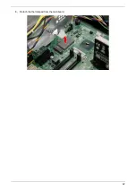
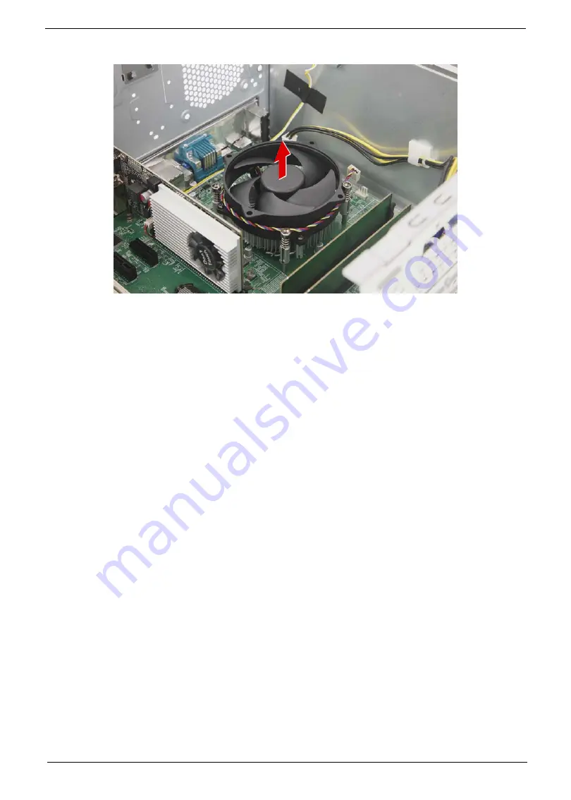
Страница 17: ...17 3 Remove the thermal module ...

Страница 18: ...ckup file of all important data WARNING The processor becomes very hot when the system is on Allow it to cool off first before handling 1 Press the load lever and move it to the right to release the load lever from the retention tab 2 Pull the load lever to release the CPU cover plate from the retaining post ...

Страница 19: ...ate 4 Lift the processor from the socket Note WEEE Annex VII component A circuit board 10 cm2 has been highlighted with the yellow rectangle as shown above Please follow local regulations for disposal of detached circuit boards ...

Страница 20: ...IMM 1 then gently pull the DIMM upward to remove it from the mainboard 2 2 Repeat Step 1 to remove the remaining memory module Note WEEE Annex VII component A circuit board 10 cm2 has been highlighted with the yellow rectangle as shown above Please follow local regulations for disposal of detached circuit boards ...

Страница 21: ...e SSD module from the mainboard Quantity Color Torque Part Number Screw Type 1 Silver 1 5 0 3 kgf cm 86 VQXD1 001 Note WEEE Annex VII component A circuit board 10 cm2 has been highlighted with the yellow rectangle as shown above Please follow local regulations for disposal of detached circuit boards ...

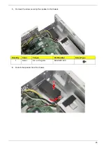
Страница 22: ...22 3 Detach the thermal pad from the mainboard ...

Страница 23: ...d 1 Remove the screw securing the expansion board bracket to the chassis 2 Unlatch the metal clip securing the expansion board bracket to the chassis Quantity Color Torque Part Number Screw Type 1 Silver 6 0 0 5 kgf cm 86 SPZD1 003 ...

Страница 24: ... x16 expansion board from its slot Note WEEE Annex VII component A circuit board 10 cm2 has been highlighted with the yellow rectangle as shown above Please follow local regulations for disposal of detached circuit boards ...

Страница 25: ...25 Removing the Speaker 1 Disconnect the speaker cable from the mainboard 2 Release the speaker cable from the plastic clip securing it to the chassis ...

Страница 26: ...26 3 Remove the screw securing the speaker to the chassis 4 Detach the speaker from the chassis Quantity Color Torque Part Number Screw Type 1 Silver 6 0 0 5 kgf cm 86 SPZD1 003 ...

Страница 27: ...27 Removing the Power Supply Module 1 Disconnect the power supply cables from the mainboard 2 Release the power supply cables from the plastic clips securing them to the chassis ...

Страница 28: ... module to the chassis 4 Remove the screw securing the front end of the power supply module to the chassis Quantity Color Torque Part Number Screw Type 2 Silver 6 0 0 5 kgf cm 86 SPZD1 003 Quantity Color Torque Part Number Screw Type 1 Silver 6 0 0 5 kgf cm 86 SPZD1 003 ...

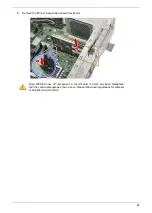
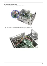
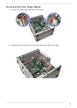
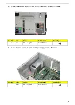
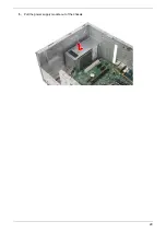
Страница 29: ...29 5 Pull the power supply module out of the chassis ...

Страница 30: ...ont I O Assembly 1 Disconnect the front I O cable from the mainboard 2 Remove the two screws securing the front I O bracket to the chassis Quantity Color Torque Part Number Screw Type 2 Silver 6 0 0 5 kgf cm 86 SPZD1 003 ...

Страница 31: ...Pull the bracket with the cables out of the chassis 4 Remove the two screws securing the SD card reader board to the bracket Quantity Color Torque Part Number Screw Type 2 Silver 6 0 0 5 kgf cm 86 BA8D1 001 ...

Страница 32: ...card reader board from the bracket Note WEEE Annex VII component A circuit board 10 cm2 has been highlighted with the yellow rectangle as shown above Please follow local regulations for disposal of detached circuit boards ...

Страница 33: ...sconnect the chassis intrusion power button LED and OBR cables from the mainboard 2 Remove the two screws securing the VGA cover to the VGA connector Quantity Color Torque Part Number Screw Type 2 Silver 4 0 0 5 kgf cm 86 VQWD1 002 ...

Страница 34: ...34 3 Detach the VGA cover from the VGA connector 4 Remove the eight screws securing the mainboard to the chassis Quantity Color Torque Part Number Screw Type 8 Silver 6 0 0 5 kgf cm 86 SPZD1 003 ...

Страница 35: ...gage the ports from the rear I O bracket 6 Gently lift the board off the chassis Note WEEE Annex VII component A circuit board 10 cm2 has been highlighted with the yellow rectangle as shown above Please follow local regulations for disposal of detached circuit boards ...

Страница 36: ...EE Annex VII component The RTC battery has been highlighted with the yellow circle as shown above Please follow local regulations for disposal of used batteries Caution Risk of explosion if battery is replaced by an incorrect type Dispose of used batteries according to the instructions ...

Отзывы: