
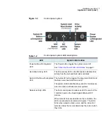
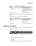


Figure 1-3
Control panel system
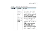
Table 1-2
Control panel system LED descriptions
System information
LED
The Power button toggles the system on and off.
See
“About the Power button LED states”
on page 8.
Power button with integrated
LED
The drive activity LED on the front panel indicates drive
activity from the on-board hard disk controllers.
Hard drive Activity LED
The System ID button toggles the integrated ID LED and
the blue server board LED on and off.
The system ID LED identifies the system for maintenance
when it is racked with similar server systems.
System ID button with integrated
LED
The front control panel includes one LED for each of the
1 GB RJ45 port on the Quad Gigabit Ethernet OCP
module.
When network links are detected on the controllers, the
LEDs are activated and remain solid green. The LEDs
blink when network activity occurs, and the amount of
network activity that occurs determines the rate at which
they blink.
Network activity LEDs
7
Hardware overview
Appliance control panel


